
Manual

WAFER-CV-D25501/N26001 3.5" Motherboard
Page 34
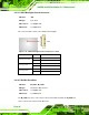
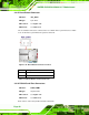
Pin Description Pin Description
7 GND 8 USB_VCC
Table 3-21: USB Connector Pinouts
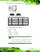
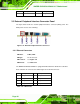
3.3 External Peripheral Interface Connector Panel
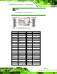
The figure below shows the external peripheral interface connector (EPIC) panel. The
EPIC panel consists of the following:
Figure 3-21: External Peripheral Interface Connector
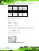
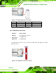
3.3.1 Ethernet Connectors
CN Label: LAN1, LAN2
CN Type:
RJ-45 connector
CN Location:
See Figure 3-21
CN Pinouts:
See Table 3-22
The WAFER-CV-D25501/N26001 is equipped with two built-in RJ-45 Ethernet controllers.
Each controller can connect to the LAN through one RJ-45 LAN connector.
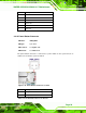
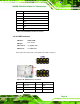
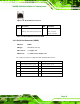
Pin Description Pin Description
1 LAN1_MDI0+ 5 LAN1_MDI2+
2 LAN1_MDI0- 6 LAN1_MDI2-
3 LAN1_MDI1+ 7 LAN1_MDI3+
4 LAN1_MDI1- 8 LAN1_MDI3-
Table 3-22: LAN Pinouts