
Manual


WAFER-CV-D25501/N26001 3.5" Motherboard
Page 20
CN Location:
See
Figure 3-6
CN Pinouts:
See
Table 3-7
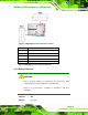
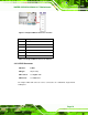
This is connected to the system battery. The battery provides power to the system clock to
retain the time when power is turned off.
Figure 3-6: Battery Connector Location
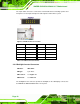
Pin Description
1 Battery+
2 GND
Table 3-7: Battery Connector Pinouts
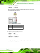
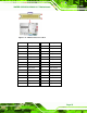
3.2.6 Digital Input/Output (DIO) Connector
CN Label: DIO1
CN Type:
10-pin header
CN Location:
See Figure 3-7
CN Pinouts:
See Table 3-8
The digital input/output connector is managed through a Super I/O chip. The DIO
connector pins are user programmable.