
Manual


WAFER-945GSE 3.5" Motherboard
Page 62
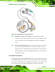
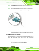
Step 2: Insert a USB Series "A" plug. Insert the USB Series "A" plug of a device into
the USB Series "A" receptacle on the external peripheral interface. See
Figure 4-20.
Figure 4-20: USB Connector
4.7.4 VGA Monitor Connection
The WAFER-945GSE has a single female DB-15 connector on the external peripheral
interface panel. The DB-15 connector is connected to a CRT or VGA monitor. To connect
a monitor to the WAFER-945GSE, please follow the instructions below.
Step 1: Locate the female DB-15 connector. The location of the female DB-15
connector is shown in Chapter 3.
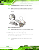
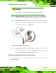
Step 2: Align the VGA connector. Align the male DB-15 connector on the VGA screen
cable with the female DB-15 connector on the external peripheral interface.
Step 3: Insert the VGA connector. Once the connectors are properly aligned with the
insert the male connector from the VGA screen into the female connector on the
WAFER-945GSE. See
Figure 4-21.