
Manual


WAFER-945GSE 3.5" Motherboard
Page 55
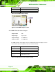
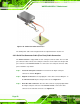
properly aligned with the connector on the adapter board. Make sure the pin 1
on the adapter board connector and the cable connector are aligned. See
Figure 4-13.
Figure 4-13: 4-COM Port Adapter Board
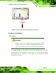
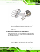
Step 4: Secure the adapter board to the chassis. Make sure the retention screws on
either side of each COM port DB-9 connector are firmly secured to the chassis
enclosure.
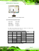
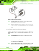
Step 5: Insert the serial connector. Insert the DB-9 connector of a serial device into
the DB-9 connector on the external peripheral interface. See
Figure 4-14.