
Manual


WAFER-945GSE 3.5" Motherboard
Page 21
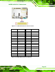
Pin Description Pin Description
20 SA0 45 66DET
21 DATA 0 46 66DET
22 DATA 1 47 DATA 8
23 DATA 2 48 DATA 9
24 N/C 49 DATA 10
25 VCC-IN CHECK2 50 GROUND
Table 3-7: CF Card Socket Pinouts
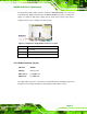
3.2.6 Digital Input/Output (DIO) Connector
CN Label: DIO1
CN Type:
10-pin header
CN Location:
See Figure 3-7
CN Pinouts:
See Table 3-8
The digital input/output connector is managed through a Super I/O chip. The DIO
connector pins are user programmable.
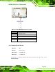
Figure 3-7: Digital I/O Connector Location
Pin Description Pin Description
1 GND 2 VCC
3 Output 3 4 Output 2
5 Output 1 6 Output 0
7 Input 3 8 Input 2
9 Input 1 10 Input 0
Table 3-8: Digital I/O Connector Pinouts