
User guide
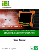

UPC-V312-D525 Panel PC
Page ix
List of Figures
Figure 1-1: UPC-V312-D525 Panel PC...........................................................................................2
Figure 1-2: Front View....................................................................................................................5
Figure 1-3: LED Indicators.............................................................................................................5
Figure 1-4: Bottom View ................................................................................................................8
Figure 1-5: Left Side View..............................................................................................................8
Figure 1-6: Left Side View..............................................................................................................9
Figure 1-7: Rear View .....................................................................................................................9
Figure 1-8: Function Key Locations ...........................................................................................10
Figure 1-9: UPC-V312-D525 Dimensions (mm)..........................................................................11
Figure 3-1: Remove the CF Card Slot Panel ..............................................................................22
Figure 3-2: CF Card Installation ..................................................................................................23
Figure 3-3: Internal USB Port Cover Retention Screws............................................................23
Figure 3-4: Pry along the Internal USB Port Cover ...................................................................24
Figure 3-5: Internal USB Port Location ......................................................................................24
Figure 3-6: Internal USB Port Installation ..................................................................................25
Figure 3-7: VESA Mount Retention Screw Holes ......................................................................26
Figure 3-8: I/O Cover Retention Screws.....................................................................................32
Figure 3-9: External Peripheral Device Connection..................................................................32
Figure 3-10: Rubber Gasket Removal.........................................................................................32
Figure 3-11: Rubber Gasket and Cable ......................................................................................33
Figure 3-12: Reinstall the I/O Cover............................................................................................33
Figure 3-13: External Peripheral Device Connection Complete ..............................................34
Figure 3-14: ACC Mode Switch ...................................................................................................34
Figure 3-15: AT/ATX Power Mode Switch ..................................................................................34
Figure 3-16: CAN-bus Terminal Block Pinouts..........................................................................35
Figure 3-17: RJ-45 Ethernet Connector......................................................................................35
Figure 3-18: LAN Connection......................................................................................................36
Figure 3-19: 3-pin Terminal Block Pinouts ................................................................................37
Figure 3-20: RJ-45 RS-232 Serial Port........................................................................................38
Figure 3-21: RJ-45 RS-232 Serial Device Connection...............................................................38
Figure 3-22: RS-422/485 Serial Port............................................................................................39