
User guide

UPC-V312-D525 Panel PC
Page 42
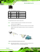
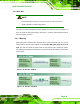
Step 3: Insert the device connector. Once aligned, gently insert the USB device
connector into the on-board connector.
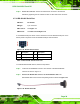
3.7.12 VGA Connector
CN Label: VGA
CN Type:
15-pin Female
CN Location:
See
Figure 1-4
CN Pinouts:
See
Figure 3-32 and Table 3-7
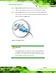
The VGA connector connects to a monitor that supports dual display. The pinouts of the
VGA connector is shown below.
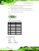
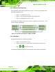
Figure 3-32: VGA Connector
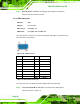
Pin Description Pin Description
1 RED 2 GREEN
3 BLUE 4 NC
5 GND 6 GND
7 GND 8 GND
9 VCC / NC 10 GND
11 NC 12 DDC DAT
13 HSYNC 14 VSYNC
15 DDCCLK
Table 3-7: VGA Connector Pinouts
To connect the UPC-V312-D525 to a second display, follow the steps below,
Step 1: Locate the female DB-15 connector. The location of the female DB-15
connector is shown in
Figure 1-4.