
User guide

UPC-V312-D525 Panel PC
Page 40
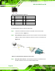
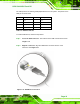
Step 3: Insert the serial connector. Insert the DB-9 connector of a serial device into
the DB-9 connector on the RS-422/485 cable.
Step 4: Secure the connector. Secure the serial device connector to the external
interface by tightening the two retention screws on either side of the connector.
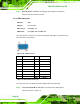
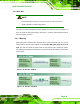
Step 5: The DB-9 connector pinouts are listed below.
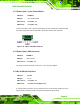
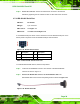
Figure 3-30: RS-422/485 Serial Port (DB-9)
Pin RS-422 RS-485
1 TX- DATA-
2 TX+ DATA+
3 RX+ --
4 RX- --
5 -- --
6 -- --
7 -- --
8 -- --
9 -- --
Table 3-5: RS-422/485 Serial Port Pinouts
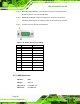
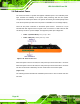
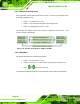
3.7.11 USB Connectors
CN Label: USB
CN Type:
USB port
CN Location:
See
Figure 1-4
CN Pinouts:
See
Table 3-6