
User guide

UPC-V312-D525 Panel PC
Page 39
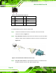
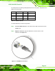
Step 4: Secure the connector. Secure the serial device connector to the external
interface by tightening the two retention screws on either side of the connector.
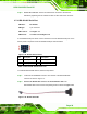
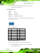
3.7.10 RS-422/485 Serial Port
CN Label: RS 422/485
CN Type:
4-pin connector
CN Location:
See
Figure 1-4
CN Pinouts:
See
Table 3-4 and Figure 3-28
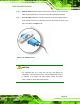
A RS-422/485 serial port device can be connected to the RS-422/485 serial port on the
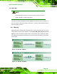
bottom panel. The pinouts of the RS-422/485 serial port is shown below.
Figure 3-28: RS-422/485 Serial Port
Pin Description Pin Description
1 RXD485+_R 3 TXD485+_R
2 RXD485#_R 4 TXD485#_R
Table 3-4: RS-422/485 Serial Port Pinouts
To install the RS-422/485 devices, follow the steps below.
Step 1: Locate the RS-422/RS485 connector. The location of the RS-422/RS-485
connector is shown in
Figure 1-4.
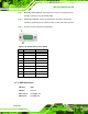
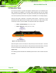
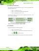
Step 2: Connect the RS-422/485 connector to the RS-422/485 cable. The
RS-422/485 cable can be found in the packing list and is shown in
Figure 3-29.
Figure 3-29: RS-422/485 Cable