
User guide

UPC-V312-D525 Panel PC
Page 38
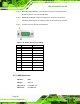
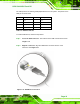
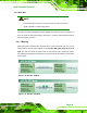
Figure 3-26: RJ-45 RS-232 Serial Port
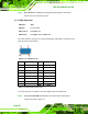
Pin Description Pin Description
1 NDCD1 5 NTX1
2 NDSR1 6 NCTS1
3. NRX1 7 NDTR1
4. NRTS1 8 NRI1
Table 3-3: RJ-45 RS-232 Serial Port Pinouts
To install the RS-232 devices, follow the steps below.
Step 1: Locate the RJ-45 RS-232 connector. The location of the RJ-45 RS-232
connector is shown in
Figure 1-4.
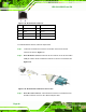
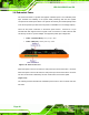
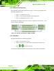
Step 2: Insert the RJ-45 connector. Insert the RJ-45 connector on the RJ-45 to DB-9
COM port cable to the RJ-45 RS-232 connector on the UPC-V312-D525. See
Figure 3-27.
Figure 3-27: RJ-45 RS-232 Serial Device Connection
Step 3: Insert the serial connector. Insert the DB-9 connector of a serial device into
the DB-9 connector on the RJ-45 to DB-9 COM port cable.