
User guide

UPC-V312-D525 Panel PC
Page 36
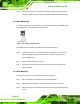
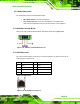
The RJ-45 Ethernet connector has two status LEDs, one green and one yellow. See
Figure 3-23.
LED Description LED Description
A on: linked
blinking: data is being sent/received
B off: 10 Mb/s
green: 100 Mb/s
orange: 1000 Mb/s
Table 3-2: RJ-45 Ethernet Connector LEDs
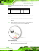
To connect the UPC-V312-D525 to a network through the RJ-45 LAN connector, follow
the steps below.
Step 1: Locate the RJ-45 connector. The location of the RJ-45 connectors is shown in
Figure 1-4.
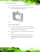
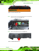
Step 2: Align the connectors. Align the RJ-45 connector on the LAN cable with one of
the RJ-45 connectors on the UPC-V312-D525. See
Figure 3-24.
Figure 3-24: LAN Connection
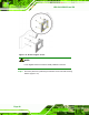
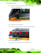
Step 3: Insert the LAN cable RJ-45 connector. Once aligned, gently insert the LAN
cable RJ-45 connector into the on-board RJ-45 connector.