
Manual


UPC-12A/GM45 Panel PC
Page 54
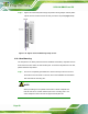
4.11.4 USB Device Connection
There are four external USB 2.0 connectors. All connectors are perpendicular to the
UPC-12A/GM45 series. To connect a USB 2.0 or USB 1.1 device, please follow the
instructions below.
Step 1: Located the USB connectors. The locations of the USB connectors are shown
in Chapter 2.
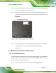
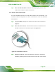
Step 2: Align the connectors. Align the USB device connector with one of the
connectors on the I/O interface panel. See
573H573H573H573H573H573H573H575HFigure 4-24.
Figure 4-24: USB Device Connection
Step 3: Insert the device connector. Once aligned, gently insert the USB device
connector into the onboard connector. Step 0:
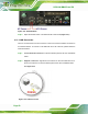
4.11.5 VGA Monitor Connection
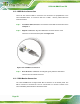
The UPC-12A/GM45 has a single female DB-15 connector on the bottom panel. The
DB-15 connector is connected to a CRT or VGA monitor. To connect a monitor to the
UPC-12A/GM45, please follow the instructions below.