
Manual


UPC-12A/GM45 Panel PC
Page 51
Step 2: Once the mounting arm has been firmly attached to the surface, lift the flat panel
PC onto the interface pad of the mounting arm.
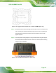
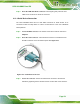
Step 3: Align the retention screw holes on the mounting arm interface with those in the
flat panel PC. The flat panel PC arm mount retention screw holes are shown in
567H567H567H567H567H567H567H569HFigure 4-20.
Figure 4-20: Arm Mounting Retention Screw Holes
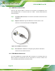
Step 4: Secure the flat panel PC to the interface pad by inserting four retention screws
through the bottom of the mounting arm interface pad and into the
flat panel PC.Step 0:
4.11 Bottom Panel Switch and Connectors
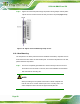
4.11.1 AT/ATX Mode Selection
AT and ATX power modes can both be used on the EP series panel PC. The selection is
made through an AT/ATX switch on the chassis rear panel (
568H568H568H568H568H568H568H570HFigure 4-21). To select AT
mode or ATX mode, follow the steps below.
Step 1: Locate the AT/ATX switch on the chassis rear panel (
569H569H569H569H569H569H569H571HFigure 4-21).