
Manual

UPC-12A/GM45 Panel PC
Page 39
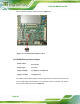
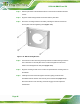
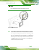
Step 3: Insert a PCI card into the PCI slot (543H543H543H543H543H543H543H545HFigure 4-8).
Step 4: Secure the PCI card with the retention screw (
544H544H544H544H544H544H544H546HFigure 4-8).
Step 5: Replace the back cover. Step 0:
4.9 Jumper Settings
NOTE:
A jumper is a metal bridge used to close an
electrical circuit. It consists of two or three metal
pins and a small metal clip (often protected by a
plastic cover) that slides over the pins to connect
them. To CLOSE/SHORT a jumper means
connecting the pins of the jumper with the plastic
clip and to OPEN a jumper means removing the
plastic clip from a jumper.
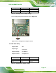
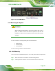
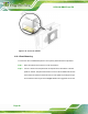
Figure 4-9: Jumper Locations
The following jumpers can be found on the motherboard installed in the UPC-12A/GM45.
Before the UPC-12A/GM45 is installed, the jumpers must be set in accordance with the
desired configuration. The jumpers on the UPC-12A/GM45 motherboard are listed in
545H545H545H545H545H545H545H547HTable 4-1.
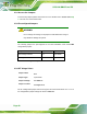
Description Label Type
CF card setup JP8 2-pin header
CF voltage select JP7 3-pin header
JP4 14-pin header COM4 function select
JP5 12-pin header
Table 4-1: Jumpers