
Instruction Manual

u IBX-210-CV-N2600 Embedded System
Page 46
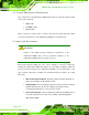
Step 9: Connect the SATA connector (JSATA2).
Step 10: Replace the back cover and secure it using eight (8) previously removed
retention screws.
5.4.2 Memory Module Replacement
If the memory module fails, follow the instructions below to replace the memory module.
Step 1: Remove eight (8) retention screws from the back cover. See Section 5.4.1.
Step 2: Remove HDD module. See Section 5.4.1.
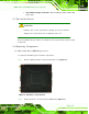
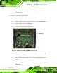
Step 3: Locate the memory module indicated below.
Figure 5-6: uIBX-210-CV-N2600 SO-DIMM Socket Location
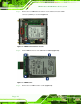
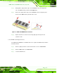
Step 4: Remove the DDR3 memory module by pulling both the spring retainer clips
outward from the socket.
Step 5: Grasp the DDR3 memory module by the edges and carefully pull it out of the
socket.
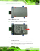
Step 6: Install the new DDR3 memory module by pushing it into the socket at an angle
(Figure 5-7).