
Instruction Manual

u IBX-210-CV-N2600 Embedded System
Page 33
4.1 Overview
This chapter details all the jumpers and connectors of the system motherboard.
4.1.1 Layout
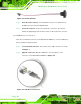
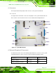
The figures below show all the connectors and jumpers of the system motherboard. The
Pin 1 locations of the on-board connectors are also indicated in the diagram below.
Figure 4-1: System Motherboard
4.2 Internal Peripheral Connectors
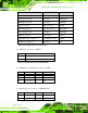
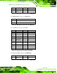
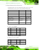
The table below shows a list of the internal peripheral interface connectors on the system
motherboard. Pinouts of these connectors can be found in the following sections.
Connector Type Label
Battery connector 2-pin wafer BAT1
BIOS programming connector 6-pin wafer SPI1