uIBX-200-R21/VX800 Embedded System IEI Technology Corp. MODEL: uIBX-200-R21/VX800 Ultra Compact Embedded System with CompactFlash® Slot VGA, Gigabit Ethernet, Four USB, 802.11b/g/n Wireless, Line out, Mic, Two RS-232, RoHS Compliant User Manual Page i Rev. 2.
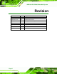
uIBX-200-R21/VX800 Embedded System Revision Date Version Changes 16 May 2011 2.10 Updated for R21 version 8 November, 2010 2.00 Updated for R20 version 23 August, 2010 1.04 Added jumper location diagrams 15 April, 2010 1.03 Added watchdog timer appendix 14 January 2010 1.02 Changed details of CF cards with embedded OS 10 September 2008 1.01 Added BIOS chapter 27 August 2009 1.
uIBX-200-R21/VX800 Embedded System Copyright COPYRIGHT NOTICE The information in this document is subject to change without prior notice in order to improve reliability, design and function and does not represent a commitment on the part of the manufacturer. In no event will the manufacturer be liable for direct, indirect, special, incidental, or consequential damages arising out of the use or inability to use the product or documentation, even if advised of the possibility of such damages.
uIBX-200-R21/VX800 Embedded System Table of Contents 1 INTRODUCTION........................................................................................................... 1 1.1 OVERVIEW.................................................................................................................. 2 1.2 BENEFITS ................................................................................................................... 2 1.3 FEATURES .............................................................
uIBX-200-R21/VX800 Embedded System 4.4.5 USB Connector ................................................................................................ 25 4.4.6 VGA Connector ................................................................................................ 26 4.5 MOUNTING THE SYSTEM .......................................................................................... 28 4.5.1 Mounting Option 1...........................................................................................
uIBX-200-R21/VX800 Embedded System 5.7.1 Northbridge VIA® VX800 Configuration ........................................................ 65 5.7.2 Southbridge VIA® VX800 Configuration ........................................................ 66 5.8 EXIT ......................................................................................................................... 66 A ONE KEY RECOVERY................................................................................................ 68 A.
uIBX-200-R21/VX800 Embedded System D.1 HAZARDOUS MATERIALS DISCLOSURE TABLE FOR IPB PRODUCTS CERTIFIED AS ROHS COMPLIANT UNDER 2002/95/EC WITHOUT MERCURY .....................................
uIBX-200-R21/VX800 Embedded System List of Figures Figure 1-1: uIBX-200-R21/VX800 ...................................................................................................2 Figure 2-1: Front Panel ..................................................................................................................6 Figure 2-2: uIBX-200-R21/VX800 Peripheral Connectors ...........................................................7 Figure 2-3: Physical Dimensions (millimeters).............................
uIBX-200-R21/VX800 Embedded System Figure A-4: Command Mode........................................................................................................74 Figure A-5: Partition Creation Commands.................................................................................75 Figure A-6: Launching the Recovery Tool .................................................................................77 Figure A-7: System Configuration for Windows ......................................................
uIBX-200-R21/VX800 Embedded System List of Tables Table 1-1: Technical Specifications..............................................................................................4 Table 3-1: Package List Contents ...............................................................................................12 Table 3-2: Optional Items.............................................................................................................13 Table 4-1: Jumpers ...........................................
uIBX-200-R21/VX800 Embedded System Chapter 1 1 Introduction Page 1
uIBX-200-R21/VX800 Embedded System 1.1 Overview Figure 1-1: uIBX-200-R21/VX800 The uIBX-200-R21/VX800 embedded system is an ultra small PC for installation between a computer screen and its stand. It is powered by the VIA® Eden™ ULV 1 GHz/500 MHz processor, uses the VIA® VX800 system chip and has 1.0 GB or 512 MB of DDR2 memory. The VIA® VX800 system chip provides many built-in graphics functions allowing high quality video playback without the need for expensive hardware.
uIBX-200-R21/VX800 Embedded System 1.3 Features The uIBX-200-R21/VX800 features are listed below: VIA® Eden™ ULV 1 GHz/500 MHz processor 1.0 GB or 512 MB of DDR2 VGA video output One Gigabit Ethernet port Four USB 2.0 ports Two RS-232 serial ports RoHS compliant 1.4 Technical Specifications The uIBX-200-R21/VX800 technical specifications are listed in Table 1-1. Specifications System CPU VIA® Eden™ ULV 1 GHz/500 MHz processor Memory 1.
uIBX-200-R21/VX800 Embedded System Specifications I/O and Communications 1 x 10/100/1000 Mb/s Ethernet 1 x 802.11b/g/n (optional) Serial Ports 2 x RS-232 USB Interfaces 4 x USB 2.
uIBX-200-R21/VX800 Embedded System Chapter 2 2 Detailed Specifications Page 5
uIBX-200-R21/VX800 Embedded System 2.1 Front Panel The front panel consists of a small door, giving access to the CompactFlash® card, and also has two USB ports, an audio output and microphone input jack. Figure 2-1: Front Panel Connectors and buttons on the front panel include the following. 1 x CompactFlash® slot 2 x USB connectors 1 x Microphone input 1 x Line output 2.
uIBX-200-R21/VX800 Embedded System Figure 2-2: uIBX-200-R21/VX800 Peripheral Connectors Connectors and buttons on the rear panel include the following.
uIBX-200-R21/VX800 Embedded System 2.3 Dimensions The physical dimensions are shown and listed below: Width: 120 mm Height: 44.
uIBX-200-R21/VX800 Embedded System 2.4 Maintenance Don't open the uIBX-200-R21/VX800 (except the CompactFlash® door), there are no user-serviceable parts inside.
uIBX-200-R21/VX800 Embedded System Chapter 3 3 Unpacking Page 10
uIBX-200-R21/VX800 Embedded System 3.1 Anti-static Precautions WARNING: Failure to take ESD precautions during installation may result in permanent damage to the uIBX-200-R21/VX800 and severe injury to the user. Electrostatic discharge (ESD) can cause serious damage to electronic components, including the uIBX-200-R21/VX800. Dry climates are especially susceptible to ESD.
uIBX-200-R21/VX800 Embedded System 3.3 Unpacking Checklist NOTE: If some of the components listed in the checklist below are missing, please do not proceed with the installation. Contact the IEI reseller or vendor you purchased the uIBX-200-R21/VX800 from or contact an IEI sales representative directly. To contact an IEI sales representative, please send an email to sales@iei.com.tw.
uIBX-200-R21/VX800 Embedded System 3.4 Optional Items Quantity Item uIBXCF-VX800-XPE Windows XP Embedded OS on Image 1 GB CompactFlash® card uIBXCF-VX800-CE060 Windows CE 6.
uIBX-200-R21/VX800 Embedded System Chapter 4 4 Installation Page 14
uIBX-200-R21/VX800 Embedded System 4.1 Installation Precautions During installation, be aware of the precautions below: Read the user manual: The user manual provides a complete description of the uIBX-200-R21/VX800, installation instructions and configuration options. DANGER! Disconnect Power: Power to the uIBX-200-R21/VX800 must be disconnected during the installation process, or before any attempt is made to access the rear panel.
uIBX-200-R21/VX800 Embedded System 4.2 Jumper Settings NOTE: A jumper is a metal bridge used to close an electrical circuit. It consists of two or three metal pins and a small metal clip (often protected by a plastic cover) that slides over the pins to connect them. To CLOSE/SHORT a jumper means connecting the pins of the jumper with the plastic clip and to OPEN a jumper means removing the plastic clip from a jumper. The hardware jumpers must be set before installation.
uIBX-200-R21/VX800 Embedded System Setting Description Open Use AT power Closed Use ATX power (Default) Table 4-2: AT/ATX Power Select Jumper Settings Figure 4-1: AT/ATX Power Select Jumper Location 4.2.2 CompactFlash® Master/Slave Selection Jumper Label: CF_MS_SEL1 Jumper Type: 3-pin header Jumper Settings: See Table 4-3 Set the CompactFlash® card as an IDE master or an IDE slave.
uIBX-200-R21/VX800 Embedded System Figure 4-2: CompactFlash® Master/Slave Switch Location 4.2.3 Clear CMOS Jumper Jumper Label: J_CMOS1 Jumper Type: 3-pin header Jumper Settings: See Table 4-4 To reset the BIOS, move the jumper to the "Clear BIOS" position for 3 seconds or more, then move back to the default position.
uIBX-200-R21/VX800 Embedded System Figure 4-3: Clear BIOS Jumper Location 4.3 CompactFlash® Card Installation The uIBX-200-R21/VX800 supports a single CompactFlash® card. To install, follow the steps below. Step 1: Unlock and open the cover door. Step 2: Slide the CompactFlash® card into the slot. Step 3: Close and lock the door.
uIBX-200-R21/VX800 Embedded System 4.4 External Peripheral Interface Connectors The uIBX-200-R21/VX800 has the following connectors. Detailed descriptions of the connectors can be found in the subsections below.
uIBX-200-R21/VX800 Embedded System Figure 4–6: Peripheral Connectors (Front) 4.4.1 Power Input The power terminal block connects to the included 5 V DC power adapter. CN Label: Power Input CN Type: Terminal block CN Location: See Figure 4-5 CN Pinouts: See Figure 4-7 Figure 4-7: Power Terminal Block 4.4.
uIBX-200-R21/VX800 Embedded System CN Location: See Figure 4–6 The audio jacks connect to external audio devices. Line Out port (Lime): Connects to a headphone or a speaker. With multi-channel configurations, this port can also connect to front speakers. Microphone (Pink): Connects a microphone. Figure 4-8: Audio Connector 4.4.3 LAN Connectors CN Label: LAN CN Type: RJ-45 CN Location: See Figure 4-5 CN Pinouts: See Table 4-5 The LAN connectors allow connection to an external network.
uIBX-200-R21/VX800 Embedded System Figure 4-9: LAN Connection Step 3: Insert the LAN cable RJ-45 connector. Once aligned, gently insert the LAN cable RJ-45 connector into the on-board RJ-45 connector. Step 0: Pin Description Pin Description 1 TXA+ 5 TXC- 2 TXA- 6 TXB- 3 TXB+ 7 TXD+ 4 TXC+ 8 TXD- Table 4-5: LAN Pinouts Figure 4-10: RJ-45 Ethernet Connector The RJ-45 Ethernet connector has two status LEDs, one green and one yellow.
uIBX-200-R21/VX800 Embedded System STATUS DESCRIPTION STATUS DESCRIPTION GREEN Activity YELLOW Linked Table 4-6: RJ-45 Ethernet Connector LEDs 4.4.4 Serial Port Connector CN Label: RS-232 CN Type: DB-9 connectors CN Location: See Figure 4-5 CN Pinouts: See Table 4-7 and Figure 4-12 RS-232 serial port devices can be attached to the DB-9 ports on the rear panel. Step 1: Locate the DB-9 connector. The location of the DB-9 connector is shown in Chapter 3. Step 2: Insert the serial connector.
uIBX-200-R21/VX800 Embedded System Step 3: Secure the connector. Secure the serial device connector to the external interface by tightening the two retention screws on either side of the connector. Pin Description Pin Description 1 DCD 6 DSR 2 RX 7 RTS 3 TX 8 CTS 4 DTR 9 RI 5 GND Step 0: Table 4-7: Serial Port Pinouts Figure 4-12: Serial Port Pinouts 4.4.
uIBX-200-R21/VX800 Embedded System Figure 4-13: USB Device Connection Step 3: Insert the device connector. Once aligned, gently insert the USB device connector into the on-board connector. Step 0: Pin Description Pin Description 1 USBV3L 5 V 2 GND 3 USBP4N 4 USBP5P 5 USBP4P 6 USBP5N 7 GND 8 USBV3L 5 V Table 4-8: USB Port Pinouts 4.4.
uIBX-200-R21/VX800 Embedded System Step 1: Locate the female DB-15 connector. The location of the female DB-15 connector is shown in Chapter 3. Step 2: Align the VGA connector. Align the male DB-15 connector on the VGA screen cable with the female DB-15 connector on the external peripheral interface. Step 3: Insert the VGA connector. Once the connectors are properly aligned with the insert the male connector from the VGA screen into the female connector on the uIBX-200-R21/VX800. See Figure 4-14.
uIBX-200-R21/VX800 Embedded System Pin Description Pin Description 7 GND 8 GND 9 VCC / NC 10 GND 11 NC 12 DDC DAT 13 HSYNC 14 VSYNC 15 DDCCLK Table 4-9: VGA Connector Pinouts 4.5 Mounting the System To install the uIBX-200-R21/VX800 on the VESA mounting slot, between the monitor stand and the monitor, follow the instructions below. 4.5.1 Mounting Option 1 Step 1: If the mounting pattern on the panel PC is VESA 100 mm then the adapter must be attached.
uIBX-200-R21/VX800 Embedded System Step 2: Fasten the attachment onto the VESA mounting on the back of the monitor. Figure 4–17: Attachment Installation Step 3: Slide the uIBX-200-R21/VX800 into the attachment and fasten the four screws indicated.
uIBX-200-R21/VX800 Embedded System Step 4: Attach the monitor and uIBX-200-R21/VX800 to a stand using the VESA mounting holes on the uIBX-200-R21/VX800. Step 0: Figure 4–19: Mounting Screws Three common methods of mounting the uIBX-200-R21/VX800 are listed in the subsections below. 4.5.2 Mounting Option 2 To install the uIBX-200-R21/VX800 on the VESA mounting slot, between the monitor stand and the monitor, follow the instructions below.
uIBX-200-R21/VX800 Embedded System Step 1: If the mounting pattern on the panel PC is VESA 100 mm then the adapter must be attached. Figure 4–20: 100 mm to 75 mm Adapter Step 2: Fasten the attachment onto the VESA mounting on the back of the monitor.
uIBX-200-R21/VX800 Embedded System Step 3: Attach the uIBX-200-R21/VX800 to the stand. Figure 4–22: System Attachment Screws Step 4: Attach the panel PC to the uIBX-200-R21/VX800. Fasten the screws on the attachment to the uIBX-200-R21/VX800. Step 0: Figure 4–23: Slide Panel PC onto uIBX-200-R21/VX800 4.6 Software Optional CompactFlash® cards with either Windows CE 6.0 or XPE are available. These include a software application development kit.
uIBX-200-R21/VX800 Embedded System operating system, adding remote management tools or additional software and drivers, refer to the utility CD. The uIBX-200-R21/VX800 includes the following software: Optional Board Support Package (BSP) for customers to customize their own OS image. Attached Software Development Kit (SDK) for embedded Visual C++ to program Windows CE application. Built-in .
uIBX-200-R21/VX800 Embedded System Chapter 5 5 BIOS Page 34
uIBX-200-R21/VX800 Embedded System 5.1 Introduction The BIOS is programmed onto the BIOS chip. The BIOS setup program allows changes to certain system settings. This chapter outlines the options that can be changed. 5.1.1 Starting Setup The AMI BIOS is activated when the computer is turned on. The setup program can be activated in one of two ways. 1. Press the DELETE key as soon as the system is turned on or 2. Press the DELETE key when the “Press Del to enter SETUP” message appears on the screen. 0.
uIBX-200-R21/VX800 Embedded System Key Function F2 /F3 key Change color from total 16 colors. F2 to select color forward. F10 key Save all the CMOS changes, only for Main Menu Table 5-1: BIOS Navigation Keys 5.1.3 Getting Help When F1 is pressed a small help window describing the appropriate keys to use and the possible selections for the highlighted item appears. To exit the Help Window press ESC or the F1 key again. 5.1.
uIBX-200-R21/VX800 Embedded System 5.2 Main The Main BIOS menu (BIOS Menu 1) appears when the BIOS Setup program is entered. The Main menu gives an overview of the basic system information. Main Advanced PCIPNP BIOS SETUP UTILITY Boot Security Chipset System Overview ⎯⎯⎯⎯⎯⎯⎯⎯⎯⎯⎯⎯⎯⎯⎯⎯⎯⎯⎯⎯⎯⎯⎯⎯⎯⎯⎯⎯⎯⎯⎯ AMIBIOS Version :08.00.14 Build Date :07/03/09 ID: :B129MR12 Exit Use [ENTER], [TAB] or [SHIFT-TAB] to select a field. Use [+] or [-] to configure system time.
uIBX-200-R21/VX800 Embedded System The System Overview field also has two user configurable fields: System Time [xx:xx:xx] Use the System Time option to set the system time. Manually enter the hours, minutes and seconds. System Date [xx/xx/xx] Use the System Date option to set the system date. Manually enter the day, month and year. 5.
uIBX-200-R21/VX800 Embedded System Main Advanced PCIPNP BIOS SETUP UTILITY Boot Security Chipset Advanced Settings ⎯⎯⎯⎯⎯⎯⎯⎯⎯⎯⎯⎯⎯⎯⎯⎯⎯⎯⎯⎯⎯⎯⎯⎯⎯⎯⎯⎯⎯⎯⎯ WARNING: Setting wrong values in below sections may cause system to malfunction > > > > > > > CPU Configuration IDE Configuration SuperIO Configuration Hardware Health Configuration Power Configuration Remote Access Configuration USB Configuration Exit Configure CPU ÅÆ ↑ ↓ Enter F1 F10 ESC Select Screen Select Item Go to SubScreen General Help Save and
uIBX-200-R21/VX800 Embedded System Frequency: Lists the CPU processing speed FSB Speed: Lists the FSB speed Cache L1: Lists the CPU L1 cache size Cache L2: Lists the CPU L2 cache size 5.3.2 IDE Configuration Use the IDE Configuration menu (BIOS Menu 4) to change and/or set the configuration of the IDE devices installed in the system.
uIBX-200-R21/VX800 Embedded System 5.3.2.1 SATA Channel Sets the IDE configuration of the SATA channels. Main Advanced PCIPNP BIOS SETUP UTILITY Boot Security Chipset Primary IDE Master ⎯⎯⎯⎯⎯⎯⎯⎯⎯⎯⎯⎯⎯⎯⎯⎯⎯⎯⎯⎯⎯⎯⎯⎯⎯⎯⎯⎯⎯⎯⎯ Device :Not Detected Type LBA/Large Mode Block (Multi-Sector Transfer) PIO Mode DMA Mode S.M.A.R.T.
uIBX-200-R21/VX800 Embedded System Î This option specifies an ATAPI Removable Media ARMD Device. These include, but are not limited to: ZIP LS-120 LBA/Large Mode [Auto] Use the LBA/Large Mode option to disable or enable BIOS to auto detects LBA (Logical Block Addressing). LBA is a method of addressing data on a disk drive. In LBA mode, the maximum drive capacity is 137 GB. Î BIOS is prevented from using the LBA mode control on Disabled the specified channel.
uIBX-200-R21/VX800 Embedded System Î Auto DEFAULT BIOS auto detects the PIO mode. Use this value if the IDE disk drive support cannot be determined. Î 0 PIO mode 0 selected with a maximum transfer rate of 3.3 MB/s Î 1 PIO mode 1 selected with a maximum transfer rate of 5.2 MB/s Î 2 PIO mode 2 selected with a maximum transfer rate of 8.3 MB/s Î 3 PIO mode 3 selected with a maximum transfer rate of 11.1 MB/s Î 4 PIO mode 4 selected with a maximum transfer rate of 16.
uIBX-200-R21/VX800 Embedded System Î Ultra DMA mode 1 selected with a maximum data transfer UDMA1 rate of 25 MB/s Î Ultra DMA mode 2 selected with a maximum data transfer UDMA2 rate of 33.3 MB/s Î Ultra DMA mode 3 selected with a maximum data transfer UDMA3 rate of 44 MB/s (To use this mode, it is required that an 80-conductor ATA cable is used.) Î Ultra DMA mode 4 selected with a maximum data transfer UDMA4 rate of 66.
uIBX-200-R21/VX800 Embedded System 5.3.3 Super IO Configuration Use the Super IO Configuration menu (BIOS Menu 6) to set or change the configurations for the FDD controllers, parallel ports and serial ports.
uIBX-200-R21/VX800 Embedded System Serial Port2 Address [2F8] Sets the port address of serial port 2. Disabled 3F8 2F8 3E8 2E8 DEFAULT Serial Port2 IRQ [3 Sets the interrupt request for serial port 2. 3 4 DEFAULT 5.3.4 Power Configuration The Power Configuration menu (BIOS Menu 7) configures the power options.
uIBX-200-R21/VX800 Embedded System ATX AT DEFAULT 5.3.4.1 ACPI Configuration Use the ACPI Configuration menu (BIOS Menu 8) to select the ACPI state when the system is suspended. Main Advanced PCIPNP BIOS SETUP UTILITY Boot Security Chipset Power Exit General ACPI Configuration ⎯⎯⎯⎯⎯⎯⎯⎯⎯⎯⎯⎯⎯⎯⎯⎯⎯⎯⎯⎯⎯⎯⎯⎯⎯⎯⎯⎯⎯⎯⎯ Suspend Mode [S1(POS)] ÅÆ ↑ ↓ Enter F1 F10 ESC Select Screen Select Item Go to SubScreen General Help Save and Exit Exit v02.61 ©Copyright 1985-2006, American Megatrends, Inc.
uIBX-200-R21/VX800 Embedded System 5.3.4.2 APM Configuration The APM Configuration menu (BIOS Menu 9) allows the advanced power management options to be configured. Main Advanced PCIPNP BIOS SETUP UTILITY Boot Security Restore on AC Power Loss Power Button Mode [Power Off] [On/Off] Resume On Ring Resume on LAN Resume on RTC Alarm [Disabled] [Disabled] [Disabled] Chipset ÅÆ ↑ ↓ Enter F1 F10 ESC Exit Select Screen Select Item Go to SubScreen General Help Save and Exit Exit v02.
uIBX-200-R21/VX800 Embedded System Î When the power button is pressed the system goes into Suspend suspend mode Resume on Ring [Disabled] Use the Resume on Ring BIOS option to enable activity on the RI (ring in) modem line to rouse the system from a suspend or standby state. That is, the system will be roused by an incoming call on a modem.
uIBX-200-R21/VX800 Embedded System 5.3.5 Remote Access Configuration Use the Remote Access Configuration menu (BIOS Menu 10) to configure remote access parameters. The Remote Access Configuration is an AMIBIOS feature and allows a remote host running a terminal program to display and configure the BIOS settings.
uIBX-200-R21/VX800 Embedded System Serial Port Number [COM1] Use the Serial Port Number option allows to select the serial port used for remote access. Î COM1 Î COM2 System is remotely accessed through COM1 DEFAULT System is remotely accessed through COM2 NOTE: Make sure the selected COM port is enabled through the Super I/O configuration menu. Base Address, IRQ [3F8h,3] The Base Address, IRQ option cannot be configured and only shows the interrupt address of the serial port listed above.
uIBX-200-R21/VX800 Embedded System Î Disabled The console is not redirected after POST Î Boot Loader Redirection is active during POST and during Boot Loader Î Always DEFAULT Redirection is always active (Some OSes may not work if set to Always) Terminal Type [ANSI] Use the Terminal Type BIOS option to specify the remote terminal type. Î ANSI Î VT100 The target terminal type is VT100 Î VT-UTF8 The target terminal type is VT-UTF8 DEFAULT The target terminal type is ANSI 5.3.
uIBX-200-R21/VX800 Embedded System Disabled Enabled DEFAULT USB 2.0 Ports Enabled [Enabled] The USB ports will only operate in the legacy USB 1.1 mode unless this setting is enabled. Disabled Enabled DEFAULT Legacy USB Support [Enabled] Use the Legacy USB Support BIOS option to enable USB mouse and USB keyboard support.
uIBX-200-R21/VX800 Embedded System 5.3.6.1 USB Mass Storage Device Configuration Use the USB Mass Storage Device Configuration menu (BIOS Menu 12) to configure USB mass storage class devices. Main Advanced PCIPNP BIOS SETUP UTILITY Boot Security Chipset Exit USB Mass Storage Device Configuration ⎯⎯⎯⎯⎯⎯⎯⎯⎯⎯⎯⎯⎯⎯⎯⎯⎯⎯⎯⎯⎯⎯⎯⎯⎯⎯⎯⎯⎯⎯⎯ USB Mass Storage Reset Delay [20 Sec] Device #1 Emulation Type M-SysT5 Dell Memory Key 5.
uIBX-200-R21/VX800 Embedded System Emulation Type [Auto] Use the Emulation Type BIOS option to specify the type of emulation BIOS has to provide for the USB device. Î Auto Î Floppy DEFAULT BIOS auto-detects the current USB. The USB device will be emulated as a floppy drive. The device can be either A: or B: responding to INT13h calls that return DL = 0 or DL = 1 respectively. Î Forced FDD Allows a hard disk image to be connected as a floppy image.
uIBX-200-R21/VX800 Embedded System Main Advanced PCIPNP BIOS SETUP UTILITY Boot Security Chipset Advanced PCI/PnP Settings ⎯⎯⎯⎯⎯⎯⎯⎯⎯⎯⎯⎯⎯⎯⎯⎯⎯⎯⎯⎯⎯⎯⎯⎯⎯⎯⎯⎯⎯⎯⎯ WARNING: Setting wrong values in below sections may cause system to malfunction IRQ3 [Reserved] IRQ4 [Reserved] IRQ5 [Available] IRQ7 [Available] IRQ9 [Available] IRQ10 [Available] IRQ11 [Available] IRQ14 [Available] IRQ15 [Available] DMA DMA DMA DMA DMA DMA Channel Channel Channel Channel Channel Channel 0 1 3 5 6 7 [Available] [Available] [Avai
uIBX-200-R21/VX800 Embedded System IRQ9 IRQ10 IRQ 11 IRQ 14 IRQ 15 DMA Channel# [Available] Use the DMA Channel# option to assign a specific DMA channel to a particular PCI/PnP device.
uIBX-200-R21/VX800 Embedded System 5.5 Boot Use the Boot menu (BIOS Menu 14) to configure system boot options. Main Advanced PCIPNP BIOS SETUP UTILITY Boot Security Chipset Boot Settings ⎯⎯⎯⎯⎯⎯⎯⎯⎯⎯⎯⎯⎯⎯⎯⎯⎯⎯⎯⎯⎯⎯⎯⎯⎯⎯⎯⎯⎯⎯⎯ > Boot Settings Configuration > > > > Boot Device Priority Hard Disk Drives CD/DVD Drives Removable Drives Exit Configure settings during system boot. ÅÆ ↑ ↓ Enter F1 F10 ESC Select Screen Select Item Go to SubScreen General Help Save and Exit Exit v02.
uIBX-200-R21/VX800 Embedded System Quick Boot [Enabled] Use the Quick Boot BIOS option to make the computer speed up the boot process. Î Disabled Î Enabled No POST procedures are skipped DEFAULT Some POST procedures are skipped to decrease the system boot time Quiet Boot [Disabled] Use the Quiet Boot BIOS option to select the screen display when the system boots.
uIBX-200-R21/VX800 Embedded System Î On DEFAULT Allows the Number Lock on the keyboard to be enabled automatically when the computer system boots up. This allows the immediate use of the 10-key numeric keypad located on the right side of the keyboard. To confirm this, the Number Lock LED light on the keyboard is lit. Boot From LAN Support [Disabled] Use the BOOT From LAN Support option to enable the system to be booted from a remote system.
uIBX-200-R21/VX800 Embedded System 5.5.3 Hard Disk Drives Use the Hard Disk Drives menu to specify the boot sequence of the available HDDs. Only installed hard drives are shown. Main Advanced PCIPNP BIOS SETUP UTILITY Boot Security Chipset Hard Disk Drives ⎯⎯⎯⎯⎯⎯⎯⎯⎯⎯⎯⎯⎯⎯⎯⎯⎯⎯⎯⎯⎯⎯⎯⎯⎯⎯⎯⎯⎯⎯⎯ > 1st Drive [Hard Drive 1] > 2nd Drive [Hard Drive 2] > 3rd Drive [Hard Drive 3] Exit Specifies the boot sequence from the available devices.
uIBX-200-R21/VX800 Embedded System 5.5.5 CD/DVD Drives Use the CD/DVD Drives menu to specify the boot sequence of the available CD/DVD drives. When the menu is opened, the CD drives and DVD drives connected to the system are listed as shown below: 1st Drive [CD/DVD: PM-(part ID)] 2nd Drive [HDD: PS-(part ID)] 3rd Drive [HDD: SM-(part ID)] 4th Drive [HDD: SM-(part ID)] NOTE: Only the drives connected to the system are shown.
uIBX-200-R21/VX800 Embedded System 5.6 Security Use the Security menu (BIOS Menu 20) to set system and user passwords. Main Advanced PCIPNP BIOS SETUP UTILITY Boot Security Chipset Exit Security Settings ⎯⎯⎯⎯⎯⎯⎯⎯⎯⎯⎯⎯⎯⎯⎯⎯⎯⎯⎯⎯⎯⎯⎯⎯⎯⎯⎯⎯⎯⎯⎯ Supervisor Password :Not Installed User Password :Not Installed Change Supervisor Password Change User Password ÅÆ ↑ ↓ Enter F1 F10 ESC Select Screen Select Item Go to SubScreen General Help Save and Exit Exit v02.61 ©Copyright 1985-2006, American Megatrends, Inc.
uIBX-200-R21/VX800 Embedded System WARNING! Setting the wrong values for the Chipset BIOS selections in the Chipset BIOS menu may cause the system to malfunction. Main Advanced PCIPNP BIOS SETUP UTILITY Boot Security Chipset Advanced Chipset Settings ⎯⎯⎯⎯⎯⎯⎯⎯⎯⎯⎯⎯⎯⎯⎯⎯⎯⎯⎯⎯⎯⎯⎯⎯⎯⎯⎯⎯⎯⎯⎯ > Northbridge VIA® VX800 Configuration > Southbridge VIA® VX800 Configuration Exit Options for VIA® VX800 ÅÆ ↑ ↓ Enter F1 F10 ESC Select Screen Select Item Go to SubScreen General Help Save and Exit Exit v02.
uIBX-200-R21/VX800 Embedded System 5.7.1 Northbridge VIA® VX800 Configuration Use the Northbridge VIA® VX800 Configuration configures the system chipset. Main Advanced PCIPNP BIOS SETUP UTILITY Boot Security Chipset Northbridge VIA® VX800 Configuration ⎯⎯⎯⎯⎯⎯⎯⎯⎯⎯⎯⎯⎯⎯⎯⎯⎯⎯⎯⎯⎯⎯⎯⎯⎯⎯⎯⎯⎯⎯⎯ VGA Frame Buffer Size [128MB] Exit Options ÅÆ ↑ ↓ Enter F1 F10 ESC Select Screen Select Item Go to SubScreen General Help Save and Exit Exit v02.61 ©Copyright 1985-2006, American Megatrends, Inc.
uIBX-200-R21/VX800 Embedded System 5.7.2 Southbridge VIA® VX800 Configuration The Southbridge VIA® VX800 Configuration configures the system chipset. Main Advanced PCIPNP BIOS SETUP UTILITY Boot Security Chipset Southbridge Configuration ⎯⎯⎯⎯⎯⎯⎯⎯⎯⎯⎯⎯⎯⎯⎯⎯⎯⎯⎯⎯⎯⎯⎯⎯⎯⎯⎯⎯⎯⎯⎯ High Definition Audio [Auto] Exit Options Disabled Auto ÅÆ ↑ ↓ Enter F1 F10 ESC Select Screen Select Item Go to SubScreen General Help Save and Exit Exit v02.61 ©Copyright 1985-2006, American Megatrends, Inc.
uIBX-200-R21/VX800 Embedded System Main Advanced PCIPNP BIOS SETUP UTILITY Boot Security Chipset Exit Options ⎯⎯⎯⎯⎯⎯⎯⎯⎯⎯⎯⎯⎯⎯⎯⎯⎯⎯⎯⎯⎯⎯⎯⎯⎯⎯⎯⎯⎯⎯⎯ Save Changes and Exit Discard Changes and Exit Discard Changes Load Optimal Defaults Load Failsafe Defaults Exit Exit system setup after saving the changes. F10 key can be used for this operation ÅÆ ↑ ↓ Enter F1 F10 ESC Select Screen Select Item Go to SubScreen General Help Save and Exit Exit v02.61 ©Copyright 1985-2006, American Megatrends, Inc.
uIBX-200-R21/VX800 Embedded System Appendix A A One Key Recovery Page 68
uIBX-200-R21/VX800 Embedded System A.1 One Key Recovery Introduction The IEI one key recovery is an easy-to-use front end for the Norton Ghost system backup and recovery tool. The one key recovery provides quick and easy shortcuts for creating a backup and reverting to that backup or for reverting to the factory default settings. The IEI One Key Recovery tool menu is shown below.
uIBX-200-R21/VX800 Embedded System A.1.1 System Requirement NOTE: The recovery CD can only be used with IEI products. The software will fail to run and a warning message will appear when used on non-IEI hardware. To create the system backup, the main storage device must be split into two partitions (three partitions for Linux).
uIBX-200-R21/VX800 Embedded System NOTE: Specialized tools are required to change the partition size if the operating system is already installed. A.1.2 Supported Operating System The recovery CD is compatible with both Microsoft Windows and Linux operating system (OS). The supported OS versions are listed below. Microsoft Windows o o o o o o Windows XP (Service Pack 2 or 3 required) Windows Vista Windows 7 Windows CE 5.0 Windows CE 6.
uIBX-200-R21/VX800 Embedded System NOTE: Installing unsupported OS versions may cause the recovery tool to fail. A.2 Setup Procedure for Windows Prior to using the recovery tool to backup or restore Windows system, a few setup procedures are required. Step 1: Hardware and BIOS setup (see Section A.2.1) 73 Step 2: Create partitions (see Section A.2.2) 73 Step 3: Install operating system, drivers and system applications (see Section A.2.3) 74 Step 4: Build-up recovery partition (see Section A.2.
uIBX-200-R21/VX800 Embedded System Step 4: Turn on the system. Step 5: Press the key as soon as the system is turned on to enter the BIOS. Step 6: Select the connected optical disk drive as the 1st boot device. (Boot Æ Boot Device Priority Æ 1st Boot Device). Step 7: Save changes and restart the computer. Continue to the next section for instructions on partitioning the internal storage.Step0: A.2.
uIBX-200-R21/VX800 Embedded System Step 3: The recovery tool setup menu is shown as below. Figure A-3: Recovery Tool Setup Menu Step 4: Press <5> then . Figure A-4: Command Mode Step 5: The command prompt window appears. Type the following commands (marked in red) to create two partitions. One is for the OS installation; the other is for saving recovery files and images which will be an invisible partition.
uIBX-200-R21/VX800 Embedded System system32>format F: /fs:ntfs /q /v:Recovery /y system32>exit Figure A-5: Partition Creation Commands Page 75
uIBX-200-R21/VX800 Embedded System NOTE: Use the following commands to check if the partitions were created successfully. Step 6: Press any key to exit the recovery tool and automatically reboot the system. Please continue to the following procedure: Build-up Recovery Partition.Step0: A.2.3 Install Operating System, Drivers and Applications Install the operating system onto the unlabelled partition.
uIBX-200-R21/VX800 Embedded System A.2.4 Build-up Recovery Partition Step 1: Put the recover CD in the optical drive. Step 2: Start the system. Step 3: Boot the system from recovery CD. When prompted, press any key to boot from the recovery CD. It will take a while to launch the recovery tool. Please be patient! Figure A-6: Launching the Recovery Tool Step 4: When the recovery tool setup menu appears, press <2> then .
uIBX-200-R21/VX800 Embedded System recovery files in Section A.2.2 is hidden and the recovery tool is saved in this 74 partition. Figure A-8: Build-up Recovery Partition Step 6: After completing the system configuration, press any key in the following window to reboot the system. Figure A-9: Press any key to continue Step 7: Eject the recovery CD.
uIBX-200-R21/VX800 Embedded System A.2.5 Create Factory Default Image NOTE: Before creating the factory default image, please configure the system to a factory default environment, including driver and application installations. To create a factory default image, please follow the steps below. Step 1: Turn on the system. When the following screen displays (Figure A-10), press 74 the key to access the recovery tool.
uIBX-200-R21/VX800 Embedded System Figure A-12: About Symantec Ghost Window Step 4: Use mouse to navigate to the option shown below (Figure A-13). 74 Figure A-13: Symantec Ghost Path Step 5: Select the local source drive (Drive 1) as shown in Figure A-14. Then click OK.
uIBX-200-R21/VX800 Embedded System Figure A-14: Select a Local Source Drive Step 6: Select a source partition (Part 1) from basic drive as shown in Figure A-15. 74 Then click OK. Figure A-15: Select a Source Partition from Basic Drive Step 7: Select 1.2: [Recovery] NTFS drive and enter a file name called iei (Figure A-16). Click Save. The factory default image will then be saved in the 74 selected recovery drive and named IEI.GHO. WARNING: The file name of the factory default image must be iei.GHO.
uIBX-200-R21/VX800 Embedded System Figure A-16: File Name to Copy Image to Step 8: When the Compress Image screen in Figure A-17 prompts, click High to make 74 the image file smaller.
uIBX-200-R21/VX800 Embedded System Step 9: The Proceed with partition image creation window appears, click Yes to continue. Figure A-18: Image Creation Confirmation Step 10: The Symantec Ghost starts to create the factory default image (Figure A-19). 74 Figure A-19: Image Creation Process Step 11: When the image creation completes, a screen prompts as shown in Figure A-20. 74 Click Continue and close the Ghost window to exit the program.
uIBX-200-R21/VX800 Embedded System Step 12: The recovery tool main menu window is shown as below. Press any key to reboot the system. Step0: Figure A-21: Press Any Key to Continue A.3 Setup Procedure for Linux The initial setup procedures for Linux system are mostly the same with the procedure for Microsoft Windows. Please follow the steps below to setup recovery tool for Linux OS. Step 1: Hardware and BIOS setup. Refer to Section A.2.1. 74 Step 2: Install Linux operating system.
uIBX-200-R21/VX800 Embedded System NOTE: Please reserve enough space for partition 3 for saving recovery images. Figure A-22: Partitions for Linux Step 3: Create a recovery partition. Insert the recovery CD into the optical disk drive. Follow Step 1 ~ Step 3 described in Section A.2.2. Then type the following 74 commands (marked in red) to create a partition for recovery images.
uIBX-200-R21/VX800 Embedded System Figure A-23: System Configuration for Linux Step 5: Access the recovery tool main menu by modifying the “menu.lst”. To first access the recovery tool main menu, the menu.lst must be modified. In Linux system, enter Administrator (root). When prompt appears, type: cd /boot/grub vi menu.lst Figure A-24: Access menu.lst in Linux (Text Mode) Step 6: Modify the menu.lst as shown below.
uIBX-200-R21/VX800 Embedded System Step 7: The recovery tool menu appears. (Figure A-25) 74 Figure A-25: Recovery Tool Menu Step 8: Create a factory default image. Follow Step 2 ~ Step 12 described in Section A.2.5 to create a factory default image. 74 A.4 Recovery Tool Functions After completing the initial setup procedures as described above, users can access the recovery tool by pressing while booting up the system. The main menu of the recovery tool is shown below.
uIBX-200-R21/VX800 Embedded System Figure A-26: Recovery Tool Main Menu The recovery tool has several functions including: 1. Factory Restore: Restore the factory default image (iei.GHO) created in Section A.2.5. 74 2. Backup system: Create a system backup image (iei_user.GHO) which will be saved in the hidden partition. 3. Restore your last backup: Restore the last system backup image 4. Manual: Enter the Symantec Ghost window to configure manually. 5. Quit: Exit the recovery tool and restart the system.
uIBX-200-R21/VX800 Embedded System A.4.1 Factory Restore To restore the factory default image, please follow the steps below. Step 1: Type <1> and press in the main menu. Step 2: The Symantec Ghost window appears and starts to restore the factory default. A factory default image called iei.GHO is created in the hidden Recovery partition. Figure A-27: Restore Factory Default Step 3: The screen is shown as in Figure A-28 when completed. Press any key to 74 reboot the system.
uIBX-200-R21/VX800 Embedded System A.4.2 Backup System To backup the system, please follow the steps below. Step 1: Type <2> and press in the main menu. Step 2: The Symantec Ghost window appears and starts to backup the system. A backup image called iei_user.GHO is created in the hidden Recovery partition. Figure A-29: Backup System Step 3: The screen is shown as in Figure A-30 when system backup is completed. 74 Press any key to reboot the system.
uIBX-200-R21/VX800 Embedded System A.4.3 Restore Your Last Backup To restore the last system backup, please follow the steps below. Step 1: Type <3> and press in the main menu. Step 2: The Symantec Ghost window appears and starts to restore the last backup image (iei_user.GHO). Figure A-31: Restore Backup Step 3: The screen is shown as in Figure A-32 when backup recovery is completed. 74 Press any key to reboot the system.
uIBX-200-R21/VX800 Embedded System A.4.4 Manual To restore the last system backup, please follow the steps below. Step 1: Type <4> and press in the main menu. Step 2: The Symantec Ghost window appears. Use the Ghost program to backup or recover the system manually. Figure A-33: Symantec Ghost Window Step 3: When backup or recovery is completed, press any key to reboot the system.
uIBX-200-R21/VX800 Embedded System A.5 Other Information A.5.1 Using AHCI Mode or ALi M5283 / VIA VT6421A Controller When the system uses AHCI mode or some specific SATA controllers such as ALi M5283 or VIA VT6421A, the SATA RAID/AHCI driver must be installed before using one key recovery. Please follow the steps below to install the SATA RAID/AHCI driver. Step 1: Copy the SATA RAID/AHCI driver to a floppy disk and insert the floppy disk into a USB floppy disk drive.
uIBX-200-R21/VX800 Embedded System Step 5: When the following window appears, press to select “Specify Additional Device”. Step 6: In the following window, select a SATA controller mode used in the system. Then press . The user can now start using the SATA HDD.
uIBX-200-R21/VX800 Embedded System Step 7: After pressing , the system will get into the recovery tool setup menu. Continue to follow the setup procedure from Step 4 in Section A.2.2 Create 74 Partitions to finish the whole setup process.Step0: A.5.2 System Memory Requirement To be able to access the recovery tool by pressing while booting up the system, please make sure to have enough system memory. The minimum memory requirement is listed below.
uIBX-200-R21/VX800 Embedded System Appendix B B Safety Precautions Page 96
uIBX-200-R21/VX800 Embedded System B.1 Safety Precautions WARNING: The precautions outlined in this appendix should be strictly followed. Failure to follow these precautions may result in permanent damage to the uIBX-200-R21/VX800. Please follow the safety precautions outlined in the sections that follow: B.1.1 General Safety Precautions Please ensure the following safety precautions are adhered to at all times.
uIBX-200-R21/VX800 Embedded System B.1.2 Anti-static Precautions WARNING: Failure to take ESD precautions during the installation of the uIBX-200-R21/VX800 may result in permanent damage to the uIBX-200-R21/VX800 and severe injury to the user. Electrostatic discharge (ESD) can cause serious damage to electronic components, including the uIBX-200-R21/VX800. Dry climates are especially susceptible to ESD.
uIBX-200-R21/VX800 Embedded System B.1.3 Product Disposal CAUTION: Risk of explosion if battery is replaced by and incorrect type. Only certified engineers should replace the on-board battery. Dispose of used batteries according to instructions and local regulations. Outside the European Union - If you wish to dispose of used electrical and electronic products outside the European Union, please contact your local authority so as to comply with the correct disposal method.
uIBX-200-R21/VX800 Embedded System Except for the LCD panel, never spray or squirt liquids directly onto any other components. To clean the LCD panel, gently wipe it with a piece of soft dry cloth or a slightly moistened cloth. The interior of the uIBX-200-R21/VX800 does not require cleaning. Keep fluids away from the uIBX-200-R21/VX800 interior. Be cautious of all small removable components when vacuuming the uIBX-200-R21/VX800.
uIBX-200-R21/VX800 Embedded System Appendix C C Watchdog Timer Page 101
uIBX-200-R21/VX800 Embedded System NOTE: The following discussion applies to DOS. Contact IEI support or visit the IEI website for drivers for other operating systems. The Watchdog Timer is a hardware-based timer that attempts to restart the system when it stops working. The system may stop working because of external EMI or software bugs. The Watchdog Timer ensures that standalone systems like ATMs will automatically attempt to restart in the case of system problems.
uIBX-200-R21/VX800 Embedded System Appendix D D Hazardous Materials Disclosure Page 103
uIBX-200-R21/VX800 Embedded System D.1 Hazardous Materials Disclosure Table for IPB Products Certified as RoHS Compliant Under 2002/95/EC Without Mercury The details provided in this appendix are to ensure that the product is compliant with the Peoples Republic of China (China) RoHS standards. The table below acknowledges the presences of small quantities of certain materials in the product, and is applicable to China RoHS only.
uIBX-200-R21/VX800 Embedded System Part Name Toxic or Hazardous Substances and Elements Lead Mercury Cadmium Hexavalent Polybrominated Polybrominated (Pb) (Hg) (Cd) Chromium Biphenyls Diphenyl (CR(VI)) (PBB) Ethers (PBDE) Housing X O O O O X Display X O O O O X Printed Circuit X O O O O X X O O O O O X O O O O X Fan Assembly X O O O O X Power Supply X O O O O X O O O O O O Board Metal Fasteners Cable Assembly Assemblies Battery O: This t
uIBX-200-R21/VX800 Embedded System 此附件旨在确保本产品符合中国 RoHS 标准。以下表格标示此产品中某有毒物质的含量符 合中国 RoHS 标准规定的限量要求。 本产品上会附有”环境友好使用期限”的标签,此期限是估算这些物质”不会有泄漏或突变”的 年限。本产品可能包含有较短的环境友好使用期限的可替换元件,像是电池或灯管,这些元 件将会单独标示出来。 部件名称 有毒有害物质或元素 铅 汞 镉 六价铬 多溴联苯 多溴二苯 (Pb) (Hg) (Cd) (CR(VI)) (PBB) 醚 (PBDE) 壳体 X O O O O X 显示 X O O O O X 印刷电路板 X O O O O X 金属螺帽 X O O O O O 电缆组装 X O O O O X 风扇组装 X O O O O X 电力供应组装 X O O O O X 电池 O O O O O O O: 表示该有毒有害物质在该部件所有物质材料中的含量均在 SJ/T11363-200