
Manual
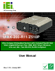


UIBX-200-R11/Z510P Embedded System
Page vii
List of Figures
Figure 1-1: UIBX-200-R11/Z510P...................................................................................................2
Figure 2-1: Front Panel ..................................................................................................................6
Figure 2-2: UIBX-200-R11/Z510P Peripheral Connectors...........................................................7
Figure 2-3: Physical Dimensions (millimeters)............................................................................8
Figure 4-1: AT/ATX Switch Location (Front Panel) ...................................................................17
Figure 4-2: CompactFlash® Card Installation ...........................................................................18
Figure 4-3: Bottom Cover Removal ............................................................................................19
Figure 4-4: SD Card Slots ............................................................................................................19
Figure 4-5: Peripheral Connectors (Rear)..................................................................................20
Figure 4–6: Peripheral Connectors (Front)................................................................................21
Figure 4-7: Power Terminal Block...............................................................................................21
Figure 4-8: Audio Connector.......................................................................................................22
Figure 4-9: LAN Connection........................................................................................................23
Figure 4-10: RJ-45 Ethernet Connector......................................................................................23
Figure 4-11: Serial Device Connector.........................................................................................24
Figure 4-12: Serial Port Pinouts..................................................................................................25
Figure 4-13: USB Device Connection .........................................................................................26
Figure 4-14: VGA Connector .......................................................................................................27
Figure 4-15: VGA Connector .......................................................................................................27
Figure 4–16: 100 mm to 75 mm Adapter ....................................................................................28
Figure 4–17: Attachment Installation..........................................................................................29
Figure 4–18: System Attachment Screws..................................................................................29
Figure 4–19: Mounting Screws....................................................................................................30
Figure 4–20: 100 mm to 75 mm Adapter ....................................................................................31
Figure 4–21: Attachment Installation..........................................................................................31
Figure 4–22: System Attachment Screws..................................................................................32
Figure 4–23: Slide Panel PC onto UIBX-200-R11/Z510P...........................................................32
Figure A-1: IEI One Key Recovery Tool Menu ...........................................................................65
Figure A-2: Launching the Recovery Tool.................................................................................69
Figure A-3: Recovery Tool Setup Menu .....................................................................................70