
Manual


UIBX-200-R11/Z510P Embedded System
Page 28
Pin Description Pin Description
7 GND 8 GND
9 VCC / NC 10 GND
11 NC 12 DDC DAT
13 HSYNC 14 VSYNC
15 DDCCLK
Table 4-8: VGA Connector Pinouts
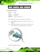
4.6 Mounting the System
To install the UIBX-200-R11/Z510P on the VESA mounting slot, between the monitor
stand and the monitor, follow the instructions below.
4.6.1 Mounting Option 1
Step 1: If the mounting pattern on the panel PC is VESA 100 mm then the adapter must
be attached.
Figure 4–16: 100 mm to 75 mm Adapter