TDM Series LCD Monitor IEI Technology Corp. MODEL: TDM Series 12.1"/15" LCD Monitor, Aluminum Front Panel Wide Range Temperature, 9~36 V DC Input User Manual Page I Rev. 2.
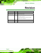
TDM Series LCD Monitor Revision Date Version Changes 8 November, 2011 2.01 Updated Section 4.4.6: RS-232 Touch Screen Connector 15 December, 2010 2.00 Updated for R20 version May 2007 1.11 -Added safety warning note for monitors used in high temperature areas (pg. iv) -AV-6600 AD Board CN25 connector pin 3 voltage changed to +9V~+36V input April 2007 1.10 Updated Chapter 4: AV-6600 AD Board December 2006 1.
TDM Series LCD Monitor Copyright COPYRIGHT NOTICE The information in this document is subject to change without prior notice in order to improve reliability, design and function and does not represent a commitment on the part of the manufacturer. In no event will the manufacturer be liable for direct, indirect, special, incidental, or consequential damages arising out of the use or inability to use the product or documentation, even if advised of the possibility of such damages.
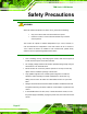
TDM Series LCD Monitor Safety Precautions WARNING: When the ambient temperature is above +50°C, please do the following: Only use monitors with a DC terminal block for power Place the monitor in a secure area accessible only to trained service persons The monitor can operate in ambient temperatures up to +50°C; however, in such environments the temperature of the LCD monitor can be in excess of +70°C.
TDM Series LCD Monitor Explosions may occur with installations in environments where flammable gases are present. Fault-tolerant and failsafe designs should be implemented with the use of the series models on transportation vehicles, ships, safety/security devices, or medical devices not related to life-support functionalities. Users/integrators should take the responsibility for implementations with adequate levels of reliability and safety.
TDM Series LCD Monitor WARNING: Any changes or modifications made to the equipment that are not expressly approved by the relevant standards could void the authority to operate the equipment. ADDITIONAL INFORMATION AND ASSISTANCE MAINTENANCE AND CLEANING Prior to cleaning any part or component of the monitor, please read the details below. Except for the properly installed front LCD panel, never spray or squirt liquids directly onto any other component.
TDM Series LCD Monitor Water or rubbing alcohol – A cloth moistened with water or rubbing alcohol can be used to clean the monitor. Using solvents – The use of solvents is not recommended when cleaning the monitor as they may damage the plastic parts. Vacuum cleaner – Using a vacuum specifically designed for computers is one of the best methods of cleaning the monitor. Over dust and dirt can restrict the airflow in a computer and cause circuitry to corrode.
TDM Series LCD Monitor Table of Contents 1 INTRODUCTION.......................................................................................................... 1 1.1 TDM-121GMS/150GMS LCD MONITOR OVERVIEW ............................................... 2 1.1.1 Standard Features .............................................................................................. 2 1.1.2 Model Variations ................................................................................................ 3 1.1.
TDM Series LCD Monitor 3 LCD AND TOUCH SCREEN SPECIFICATIONS .................................................. 19 3.1 LCD SPECIFICATIONS ............................................................................................... 20 3.1.1 LCD Overview ................................................................................................. 20 3.1.2 TDM-121GMS LCD Specifications ................................................................. 20 3.1.3 TDM-150GMS LCD Specifications ..............
TDM Series LCD Monitor 5.1 USER MODE OSD STRUCTURE ................................................................................. 48 5.1.1 OSD Buttons..................................................................................................... 48 5.1.2 OSD Menu Structure ........................................................................................ 50 5.2 USING THE OSD....................................................................................................... 51 5.2.
TDM Series LCD Monitor List of Figures Figure 1-1: Front View ....................................................................................................................5 Figure 1-2: Rear View .....................................................................................................................6 Figure 1-3: Top View.......................................................................................................................7 Figure 1-4: Bottom View .........................
TDM Series LCD Monitor Figure 5-3: Color Options ............................................................................................................52 Figure 5-4: OSD Configurations Menu .......................................................................................53 Figure 6-1: Setup Icon ..................................................................................................................56 Figure 6-2: Welcome Screen ...........................................................
TDM Series LCD Monitor List of Tables Table 1-1: TDM Series Model Variants..........................................................................................3 Table 1-2: TDM Series Specifications.........................................................................................10 Table 2-1: General Physical Dimensions ...................................................................................14 Table 2-2: TDM Series Mounting Kits ........................................................
TDM Series LCD Monitor Chapter 1 1 Introduction Page 1
TDM Series Monitor 1.1 TDM-121GMS/150GMS LCD Monitor Overview The TDM series is a Liquid Crystal Display (LCD) module. It is the latest member of IEI’s line of RoHS-compliant sophisticated LCD designs. Utilizing the thin film transistor (TFT) technology, the TDM series offers crisp displays and bright resolutions while meeting the demanding operating requirements of rugged industrial applications.
TDM Series Monitor 1.1.2 Model Variations The TDM LCD series has four model variations listed in Table 1-1. Model Number LCD Size 9~36V Touch Power Screen with RS-232 Input Interface VGA DVI TDM-121GMS-R20 12.1” Yes Yes Yes Yes TDM-150GMS-R20 15” Yes Yes Yes Yes Table 1-1: TDM Series Model Variants 1.1.3 Applications The TDM series industrial monitor is designed for rigorous industrial environments where it may be exposed to both heat and moisture.
TDM Series Monitor 1.1.
TDM Series Monitor 1.2.1 Front View The front of the TDM series industrial monitor is a flat panel TFT LCD screen surrounded by an aluminum frame. A control button panel (OSD) is located vertically on the right side of the frame with the following control buttons: LCD On/Off Auto Left Right Menu The OSD panel also has one power LED. Figure 1-1 shows the LCD monitor front view.
TDM Series Monitor 1.2.2 Rear View The rear panel features fan ventilation holes and four retention screw holes that support a wall-mounting bracket. The retention screw holes are circled in Figure 1-2.
TDM Series Monitor 1.2.3 Top View The top view provides access to retention screws that secure the back cover to the chassis. The retention screw holes are circled in Figure 1-3 below. Figure 1-3: Top View 1.2.4 Bottom View The bottom view provides access to retention screws that secure the back cover to the chassis. The retention screw holes are circled in Figure 1-4 below. Figure 1-4: Bottom View 1.2.5 Side View The rear panel shown in Figure 1-5 has the following interfaces. See Section 5.4.
TDM Series Monitor Figure 1-5: Side View 1.2.6 Frame An aluminum frame surrounds the TDM series LCD monitor. This aluminum frame has small screw holes that are used to attach the LCD monitor to a rack mount kit for mounting into a rack or cabinet. The screw holes on TDM-121GMS are circled in Figure 1-6.
TDM Series Monitor Figure 1-7: TDM-150GMS Frame Rear View (6 rack mount kit screw holes) 1.2.7 Internal View The TDM series industrial monitor AD board provides a wide variety of control interfaces, receiving and managing signals from a CPU card through cabling. Refer to Section 3.3 for a complete description of the AV-6600 AD board and its connectors. 1.3 Series Specifications Table 1-2 shows the TDM Series specifications. Model TDM-121GMS TDM-150GMS LCD Size 12.
TDM Series Monitor Model TDM-121GMS TDM-150GMS View Angle 160/160 140/125 Aluminum Front Frame Heavy-duty steel Chassis Input Voltage 9~36VDC OSD Function Yes Wall / Panel / Rack / Arm / Stand Mounting Silver Color Dimension (mm) 340 x 260 x 58 410 x 309x 65.2 Operation Temperature -30°C~70°C Storage Temperature -40°C~80°C IP 65 IP Level 3.3kg Net Weight 6kg Table 1-2: TDM Series Specifications 1.
TDM Series Monitor Chapter 2 2 Detailed Specifications Page 11
TDM Series Monitor 2.1 Introduction This chapter describes the general mechanical overview of the TDM series monitors including front and rear panel, available interfaces and overall dimensions. 2.2 Front Panel The front panel of the TDM series industrial monitor is comprised of a TFT LCD with LED backlight in an aluminum frame with an OSD control panel. Figure 2-1 shows the front panel of the TDM series.
TDM Series Monitor 2.3 Rear Panel All peripheral device connectors are located on the rear panel of the TDM series industrial monitor. The following rear panel connectors may be found on the TDM series. Figure 2-2 shows the location of the connectors.
TDM Series Monitor 2.4 Physical Dimensions The following sections describe the physical dimensions for each model of the TDM series industrial monitor. 2.4.1 General Physical Dimensions General physical dimensions for the TDM series industrial monitors are shown in Table 2-1. Model Width Height Depth (mm) (mm) (mm) TDM-121GMS 340 260 58 TDM-150GMS 410 309 65.
TDM Series Monitor 2.4.2 TDM-121GMS Physical Dimensions The physical dimensions of the TDM121GMS are shown in Figure 2-3.
TDM Series Monitor 2.4.3 TDM-150GMS Physical Dimensions The physical dimensions of the TDM-150GMS are shown in Figure 2-4.
TDM Series Monitor 2.5 Mounting Kits The following sections describe the various optional mounting kits available for each model of the TDM series industrial monitor. Refer to Section 4.4.7 for detailed instructions on the different mounting methods for the monitors. Table 2-2 lists the mounting kits available for the TDM series monitor.
TDM Series Monitor Model Mounting Clamps TDM-121GMS 10 TDM-150GMS 10 Table 2-3: Panel Mounting Clamps 2.6.2 Rack and Cabinet Mounting Each model of the TDM series industrial monitor has a series of holes located on the rear of the front panel for securing the monitor to the rack mounting kit. Table 2-4 lists the number of holes each monitor has to secure the monitor to the rack mounting kit. Model Holes TDM-121GMS 4 TDM-150GMS 6 Table 2-4: Rack Mounting Holes 2.6.
TDM Series Monitor Chapter 3 3 LCD and Touch Screen Specifications Page 19
TDM Series Monitor 3.1 LCD Specifications 3.1.1 LCD Overview The TDM series industrial monitors use the following LCD panels. TDM-121GMS: AUO G121XN01 V0 TDM-150GMS: AUO G150XG01 V1 Detailed specifications for the LCD screens are listed in the following sections. 3.1.2 TDM-121GMS LCD Specifications Table 3-1 lists the LCD specifications of the TDM-121GMS. Model Size TDM-121GMS 12.1” MFR/Model AUO/G121XN01 V0 Resolution XGA (1024 x 768) Active Area (mm) Pixel Pitch (mm) Mode 245.76 x 184.
TDM Series Monitor 3.1.3 TDM-150GMS LCD Specifications Table 3-2 lists the LCD specifications of the TDM-150GMS. Model Size TDM-121GMS 15” MFR/Model AUO/G150XG01 V1 Resolution XGA (1024 x 768) Active Area (mm) Pixel Pitch (mm) Mode Number of Colors Color Saturation (NTSC%) View Angle (H/V) Brightness (cd/m2) Contrast Ratio Response Time (ms) (at 25C) Power Consumption (W) Interface Supply Voltage (V) 304.1 x 228.1 0.297 TN 16.2M 65 140/120 350 700:1 8 8.9 1ch LVDS 3.
TDM Series Monitor 3.2 Touch Screens The TDM series industrial monitors all preinstalled with touch screens with the following features: 8-wire touch screen Small border customized design All size touch screen design Customized activation force and palm rejection Customized optical characteristics High reliability and durability in the field 3.
TDM Series Monitor Figure 3-1: AV-6600 AD Board Overview 3.3.1 AV-6600 Peripheral Interface Connectors Table 3-3 shows a list of the peripheral interface connectors on the AV-6600 AD board.
TDM Series Monitor Infrared connector 6-pin wafer connector CN8 Inverter interface connector 6-pin wafer connector CN6 LVDS connector 30-pin connector CN5 Power output connector (+12 V) 2-pin wafer connector CN3 Power output connector (+5 V) 2-pin wafer connector CN4 Power input connector 3-pin connector CN2 RS-232 and USB signal input connector 12-pin wafer connector CN14 Touchscreen connector 9-pin wafer connector J4 VGA connector 10-pin box header VGA2 Table 3-3: AV-6600 Periph
TDM Series Monitor Chapter 4 4 Installation Page 25
TDM Series Monitor 4.1 Installation Precautions When installing the TDM series industrial monitor, please follow the precautions listed below: Read the user manual: The user manual provides a complete description of the TDM series industrial monitor, installation instructions and configuration options. DANGER! Disconnect Power: Power to the monitor must be disconnected when installing the TDM series industrial monitor, or before any attempt is made to access the rear panel.
TDM Series Monitor 4.2 Unpacking 4.2.1 Packaging When shipped, the TDM series industrial monitor is wrapped in a plastic bag. Two polystyrene ends are placed on either side of the monitor. The monitor is then placed into a first (internal) cardboard box. This box is then sealed and placed into a second (external) cardboard box. The second box is also sealed. A bag containing accessory items is placed underneath the monitor, at the bottom of the internal (first) box. 4.2.
TDM Series Monitor 4.2.3 Packing List All the monitors in the TDM series are shipped with the following components: TDM-121GMS / TDM-121GMS/T-R / TDM-150GMS / TDM-150GMS/T-R industrial LCD monitor 1 x Power cable for terminal block 1 x VGA cable 1 x Screw set 1 x User manual on CD-ROM 1 x Touch screen RS-232 cable / touch pen / driver CD-ROM (T-R models only) *1 x 45W AC power adapter with AC 90V ~ 264V @ 1A input and DC +12V @3.
TDM Series Monitor 4.3.2 Voltage Select Jumper Settings If the monitor comes with both 12V and 9 ~ 36V DC power connectors, the voltage select jumper on the integrated AD board must be configured for the DC connector that is used to power the monitor. Refer to Section 4.3.2 for the appropriate jumper settings of the AD board. NOTE: The default voltage select jumper is configured for a 12V power source.
TDM Series Monitor 4.4 Connectors Table 4-1 lists the external peripheral interface panel connectors for the TDM series industrial monitors.
TDM Series Monitor 4.4.1 Rear Panel Connectors Overview Figure 4-1: Monitor Rear Panel Connections Figure 4-1 shows all the possible rear panel connectors for the TDM series LCD monitor. The following sections fully describe the rear panel connectors for the TDM series LCD monitor. 4.4.2 VGA Connector Use the rear panel standard 15-pin female VGA connector to connect the monitor to the system graphics interface. See Section 4.2.8 for the VGA connector location and pinouts.
TDM Series Monitor 4.4.3 DVI-D Connector Use the rear panel standard 24-pin female DVI-D connector to connect the monitor to the system graphics interface. See Section 4.4.3 for the DVI-D connector location and pinouts. 4.4.4 12V Power Connector Use the rear panel +12V DC jack to connect the monitor to a power source. Figure 4-2: 12V Power Connector 4.4.5 DC Power Connector Use the rear panel 3-pin terminal block DC power connector to connect the monitor to a DC power source.
TDM Series Monitor 4.4.6 RS-232 Touch Screen Connector Use the rear panel standard RS-232 DB-9 female touch screen connector to connect the monitor to the system graphics interface. PIN DESCRIPTION PIN DESCRIPTION 1 N/A 6 NDSR 2 NRX 7 NRTS 3 NTX 8 N/A 4 NDTR 9 N/A 5 GND Table 4-2: RS-232 Touch Screen Connector Pinouts Figure 4-4: RS-232 Touch Screen Connector 4.4.
TDM Series Monitor Figure 4-5: USB Touch Screen Connector 4.5 Mounting the TDM Series LCD Monitor The TDM series LCD monitor can be mounted in a panel, cabinet, rack, or wall. The monitor can also be mounted on a monitor arm or stand. The mounting methods are described below. CAUTION: When mounting the monitor take care to tighten the retention screws or bolts until fully secure, but do not over tighten.
TDM Series Monitor Figure 4-6: Panel Opening Page 35
TDM Series Monitor Step 3: Slide the monitor through the hole until the metal frame is flushed against the panel (Figure 4-7).
TDM Series Monitor Step 4: Insert the panel mounting clamps into the pre-formed holes along the edges of the monitor, behind the metal frame. Figure 4-8 shows the location of clamp insertion holes on one side of the LCD monitor. Refer to Table 2-3 for the mounting clamps required for each model.
TDM Series Monitor Step 5: Tighten the screws that pass through the panel mounting clamps until the plastic caps at the front of all the screws are firmly secured to the panel (Figure 4-9). Figure 4-9: Panel Mounting Clamp Position 4.5.2 Cabinet and Rack Installation The TDM series provides optional rack mount kits for industrial racks. To mount the TDM series LCD monitor into a cabinet/rack, please follow the steps below.
TDM Series Monitor Step 4: Secure the rack mount kit to the monitor by inserting and tightening the retention screws (Figure 4-10).
TDM Series Monitor Step 5: Slide the monitor with the attached rack mount kit into a rack or cabinet (Figure 4-11). Figure 4-11: Install into a Cabinet/Rack Step 6: Once the monitor with the attached cabinet/rack has been properly inserted into the rack or cabinet, secure the front of the rack/cabinet bracket to the front of the rack or cabinet (Figure 4-11). 4.5.3 Wall Mounting To mount the TDM series industrial monitor onto a wall, please follow the steps below.
TDM Series Monitor Step 4: Align the wall-mounting bracket screw holes with the pilot holes. Step 5: Secure the mounting-bracket to the wall by inserting the retention screws into the four pilot holes and tightening them (Figure 4-12). Figure 4-12: Wall-mounting Bracket Step 6: Insert the four monitor mounting screws provided in the wall mounting kit into the four screw holes on the real panel of the monitor and tighten until the screw shank is secured against the rear panel (Figure 4-13).
TDM Series Monitor Figure 4-13: Monitor Support Screws Step 7: Align the mounting screws on the monitor rear panel with the mounting holes on the bracket. Step 8: Carefully insert the screws through the holes and gently pull the monitor downwards until the monitor rests securely in the slotted holes (Figure 4-14). Ensure that all four of the mounting screws fit snuggly into their respective slotted holes.
TDM Series Monitor Figure 4-14: Wall Mounting the Monitor 4.5.4 Monitor Stand Installation The TDM series industrial monitor has Video Electronics Standards Association (VESA) standard mounting holes tapped into the rear panel. The standard holes are M4 set at 100m x 100mm apart (Figure 4-15).
TDM Series Monitor Figure 4-15: VESA Mounting Holes The monitor stand mounting plate has a matching VESA hole pattern. To mount the TDM series industrial monitor onto a stand, please follow the steps below. Step 1: Line up the threaded holes on the monitor rear panel with the screw holes on the monitor stand mounting plate. Step 2: Secure the monitor to the stand with the supplied retention screws (Figure 4-16).
TDM Series Monitor Figure 4-16: Monitor Stand Mounting 4.5.5 Monitor Arm Installation The TDM series industrial monitor has Video Electronics Standards Association (VESA) standard mounting holes tapped into the rear panel. The standard holes are M4 set at 100m x 100mm apart (Figure 4-15). The monitor arm mounting plate has a matching VESA hole pattern. To mount the TDM series industrial monitor onto a monitor arm, please follow the steps below.
TDM Series Monitor Step 1: Line up the threaded holes on the monitor rear panel with the screw holes on the monitor arm mounting plate. Step 2: Secure the monitor to the arm with the supplied retention screws (Figure 4-17).
TDM Series Monitor Chapter 5 5 On-Screen-Display (OSD) Controls Page 47
TDM Series Monitor 5.1 User Mode OSD Structure 5.1.1 OSD Buttons There are several on-screen-display (OSD) control buttons oriented either vertically along the right hand side of the monitor front panel. Figure 5-1 shows a typical arrangement of OSD controls. Figure 5-1: OSD Control Buttons for All Models Menu/Enter Button Press this button to open the OSD window. When inside a menu, press this button to confirm the function adjustment or selection of the item. There may be several levels in one item.
TDM Series Monitor Left Button Press this button to scroll to the left, to increase the value, or to switch from one selected item to another. Auto/Exit Button Press this button to enable auto-configuration or apply default values. LCD ON/OFF Button Press this button to turn the LCD monitor on or off.
TDM Series Monitor 5.1.2 OSD Menu Structure Table 5-1 shows the OSD menu structure for all models of the TDM series LCD monitor. Level 0 Level 1 Value Main Display Features Menu Brightness 0 to 100 Contrast 0 to 100 Clock 0 to 100 Phase 0 to 100 H. Position 0 to 100 V.
TDM Series Monitor 5.2 Using the OSD OSD menu options are described below. 5.2.1 Main Display Features Main display features are shown in Figure 5-2. Figure 5-2: Main Display Features The brightness option adjusts the brightness of screen. This function Brightness adjusts the offset value of ADC. Setting this value too high or too low will affect the quality of image. When the auto- dimming function is turned on, the brightness control is not effective.
TDM Series Monitor 5.2.2 Color Color options are shown in Figure 5-3. Figure 5-3: Color Options The Color menu fine-tunes the palette of color hues for the LCD. 6500k NTSC standard Kelvin 7500k NTSC standard Kelvin 9300k NTSC standard Kelvin User Page 52 This item allows fine-tuning the balance among Red, Green, and Blue color hues if images look garish or unrealistic.
TDM Series Monitor 5.2.3 OSD Configurations The OSD configurations are shown in Figure 5-4. Figure 5-4: OSD Configurations Menu OSD Configurations are described below. OSD Time Out Determines how many seconds the OSD screen stays on screen before it disappears when OSD is left unattended. Adjusts the OSD position on the screen. Position 1 is in the upper left OSD Position of the screen, position 2 in the upper right and position 3 in the center.
TDM Series Monitor Chapter 6 6 Software Drivers Page 54
TDM Series Monitor 6.1 Introduction The touch panel controller enables analog resistive touch panels for four-wire, five-wire & eight-wire models. The controller directly communicates with the PC system through the touch panel communications interface. The controller design is superior in sensitivity, accuracy, and friendly operation. The touch panel driver emulates the left mouse button and the right mouse button functions.
TDM Series Monitor USB Interface: If the touch screen interface connection is a USB connection, connect the USB connector on the single board computer to the external USB port connector of the TDM Series monitor. 6.3 Touch Panel Driver Installation WARNING: Before the touch screen driver is installed, make sure the system is connected to the monitor with a USB cable or an RS-232 null cable. Also, make sure the VGA connector on the system is connected to the VGA connector on the bottom of the monitor.
TDM Series Monitor Step 4: Double click the setup icon in Figure 6-1. Step 5: The Welcome screen in Figure 6-2 appears. Figure 6-2: Welcome Screen Step 6: Click Next to continue. Step 7: The license agreement in Figure 6-3 appears. Accept the terms of the agreement by clicking I Agree.
TDM Series Monitor Step 8: The installation destination screen appears. See Figure 6-4. Click Install. Figure 6-4: Initiate Install Step 9: The installation of the program begins. See Figure 6-5. Figure 6-5: Installation Starts Step 10: When the installation is complete, the complete screen appears. See Figure 6-6. To complete the installation process click Finish.
TDM Series Monitor Figure 6-6: Finish Installation 6.4 Change the Touch Screen Interface If the touch screen interface must be changed from an RS-232 interface to a USB interface or, from a USB interface to an RS-232 interface, the following steps must be followed. Step 1: Uninstall the touch screen driver Step 2: Remove the interface cable i.e. remove the RS-232 cable or the USB cable Step 3: Install the new cable i.e. install the USB cable or the RS-232 cable.
TDM Series Monitor Step 3: Locate the PenMount Monitor icon in the bottom left corner of the screen. Figure 6-7: PenMount Monitor Icon Step 4: Click the icon. A pop up menu appears. See Figure 6-8. Figure 6-8: PenMount Monitor Popup Menu Step 5: Click Control Panel in the pop up menu shown in Figure 6-8. Step 6: The configuration screen in Figure 6-9 appears.
TDM Series Monitor Step 7: Double click the PenMount 6000 icon as shown in Figure 6-9. Step 8: The calibration initiation screen in Figure 6-10 appears. Step 9: Select the Standard Calibration button as shown in Figure 6-10. Figure 6-10: Calibration Initiation Screen Step 10: The calibration screen in is shown. See Figure 6-11. Figure 6-11: Calibration Screen Step 11: Follow the instructions. The user is asked touch the screen at five specified points after which the screen is calibrated.
TDM Series Monitor Chapter 6 7 7 Gasket Replacement Page 62
TDM Series Monitor 7.1 Gasket Replacement A gasket used for a long time may gradually lose its ability to protect the monitor from fluids and vapors; scratches or dirt may also accumulate. It is recommended that the gasket be replaced yearly. NOTE: If the monitor is mounted vertically, first remove it and place it on a flat, level surface with the display screen facing down before changing the gasket. Step 1: Remove the old gasket from the sides of the monitor.
TDM Series Monitor Appendix A A Certifications Page 64
TDM Series Monitor A.1 RoHS Compliant All models in the TDM LCD monitor series comply with the Restriction of Hazardous Materials (RoHS) Directive. This means that all components used to build the industrial workstations and the workstation itself are RoHS compliant.