
User Manual
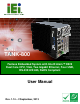


TANK-800 Embedded System
Page ix
List of Figures
Figure 1-1: TANK-800.....................................................................................................................2
Figure 1-2: TANK-800 Peripheral Connectors .............................................................................6
Figure 1-3: TANK-800 LED Indicators...........................................................................................7
Figure 1-4: TANK-800-D525/1GB/2P1E-R10 Backplane (HPE-3S6) ...........................................8
Figure 1-5: TANK-800-D525/1GB/1P2E-R10 Backplane (HPE-3S7) ...........................................8
Figure 1-6: Physical Dimensions (millimeters)..........................................................................10
Figure 3-1: CF Card Slot ..............................................................................................................18
Figure 3-2: CF Card Slot Cover ...................................................................................................18
Figure 3-3: CF Card Installation ..................................................................................................19
Figure 3-4: Unscrew the Cover....................................................................................................20
Figure 3-5: Remove the Cover from TANK-800 .........................................................................20
Figure 3-6: HDD Installation ........................................................................................................21
Figure 3-7: HDD Retention Screws .............................................................................................21
Figure 3-8: Remove the HDD Bracket from the Cover..............................................................22
Figure 3-9: Remove the Fan Bracket from the Cover ...............................................................23
Figure 3-10: Remove the Temporary Retaining Bracket ..........................................................23
Figure 3-11: Secure the System Fan to the Fan Bracket..........................................................24
Figure 3-12: Reinstall the Fan Bracket.......................................................................................24
Figure 3-13: Pluggable DC-in Terminal Block Installation .......................................................25
Figure 3-14: Mounting Bracket Retention Screws ....................................................................26
Figure 3-15: ACC Mode Switch ...................................................................................................28
Figure 3-16: AT/ATX Power Mode Switch ..................................................................................28
Figure 3-17: Audio Connector.....................................................................................................29
Figure 3-18: DIO Connector Pinout Location ............................................................................30
Figure 3-19: LAN Connection......................................................................................................31
Figure 3-20: RJ-45 Ethernet Connector......................................................................................31
Figure 3-21: 3-pin Terminal Block Pinout Location ..................................................................32
Figure 3-22: Power Input Connector...........................................................................................33
Figure 3-23: RJ-45 RS-422/485 Serial Device Connection........................................................34
Figure 3-24: RJ-45 RS-422/485 Serial Port Pinout Location.....................................................34