
User Manual


TANK-800 Embedded System
Page 27
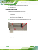
Step 3: Secure the brackets to the system by inserting two retention screws into each
bracket (
Figure 3-14).
Step 4: Drill holes in the intended installation surface.
Step 5: Align the mounting holes in the sides of the mounting brackets with the predrilled
holes in the mounting surface.
Step 6: Insert four retention screws, two in each bracket, to secure the system to the
wall.
3.7 External Peripheral Interface Connectors
The TANK-800 has the following connectors. Detailed descriptions of the connectors can
be found in the subsections below.
Audio
CompactFlash® Type II
DIO
Ethernet
Power button
Power input
Reset button
RS-232
RS-422/485
USB
VGA