
Instruction Manual

TANK-700 Embedded System
Page 19
Step 6: Reconnect the SATA signal and power cables to the TANK-700.
Step 7: Reinstall the bottom panel to the TANK-700.
3.3 Pluggable CAN-bus Terminal Block Ins tallation
To install the pluggable CAN-bus terminal block, please follow the steps below:
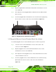
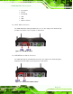
Step 1: Locate the CAN-bus terminal block connector. The location of the connector is
shown in Figure 1-2.
Step 2: Align the pluggable CAN-bus terminal block with the CAN-bus terminal block
connector on the TANK-700.
Step 3: Once aligned, insert the pluggable CAN-bus terminal block into the CAN-bus
terminal block connector.
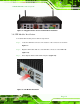
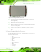
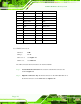
Step 4: Secure the pluggable CAN-bus terminal block to the external interface by
tightening the two retention screws on either side of the terminal block
(Figure 3-5).
Figure 3-5: Pluggable CAN-bus Terminal Block Installation
3.4 Pluggable DC-In Terminal Block Ins tallation
To install the pluggable DC-in terminal block, please follow the steps below:
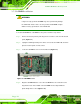
Step 1: Locate the DC-in terminal block connector. The location of the connector is
shown in Figure 1-3.