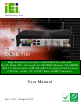
TANK-700 Em b e d de d S ys te m IEI Te c h n o lo g y Co rp . MODEL: TANK-700 Hig h P e rfo rm a n c e Fa n le s s Em b e d d e d S ys te m with In te l® 32n m CP U, On -b o a rd 2.0 GB DDR3 Me m o ry, VGA/HDMI, US B 3.0, Du a l Co m b o (S FP Fib e r/RJ -45) Gig a b it LAN, Is o la te d CAN-b u s , Au d io , 9V~36V DC In p u t, Ro HS Co m p lia n t Us e r Ma n u a l Page i Re v. 2.
TANK-700 Em b e d d e d S ys te m Re vis io n Date Version Changes 28 April, 2013 2.00 Update Section 3.2: Hard Disk Drive (HDD) Installation 18 December, 2012 1.12 Updated Section 3.9.11: Remote Control Connector 15 October, 2012 1.11 Updated memory spec 5 December, 2011 1.10 Updated Section 2.3: Unpacking Checklist Updated Section 3.9.13: RJ-45 RS-422/485 Serial Ports Updated Appendix A: One Key Recovery 17 October, 2011 P a g e ii 1.
TANK-700 Em b e d de d S ys te m Co p yrig h t COP YRIGHT NOTICE The information in this document is subject to change without prior notice in order to improve reliability, design and function and does not represent a commitment on the part of the manufacturer. In no event will the manufacturer be liable for direct, indirect, special, incidental, or consequential damages arising out of the use or inability to use the product or documentation, even if advised of the possibility of such damages.
TANK-700 Em b e d d e d S ys te m WARNING This device complies with Part 15 of the FCC Rules. Operation is subject to the following two conditions: (1) this device may not cause harmful interference, and(2) this device must accept any interference received, including interference that may cause undesired operation. NOTE: This equipment has been tested and found to comply with the limits for a Class B digital device, pursuant to part 15 of the FCC Rules.
TANK-700 Em b e d de d S ys te m Ta b le o f Co n te n ts 1 INTRODUCTION.......................................................................................................... 1 1.1 OVERVIEW.................................................................................................................. 2 1.2 MODEL VARIATIONS ................................................................................................... 2 1.3 FEATURES .................................................................
TANK-700 Em b e d d e d S ys te m 3.9.6 Digital Input/Output Connector ....................................................................... 27 3.9.7 HDMI Connector ............................................................................................. 27 3.9.8 LAN Connectors ............................................................................................... 28 3.9.9 Power Input, 4-pin Terminal Block .................................................................. 30 3.9.
TANK-700 Em b e d de d S ys te m 4.3.4 SATA Configuration ......................................................................................... 55 4.3.5 USB Configuration........................................................................................... 56 4.3.6 Second Super IO Configuration ....................................................................... 58 4.3.6.1 Serial Port n Configuration ....................................................................... 58 4.3.
TANK-700 Em b e d d e d S ys te m A.6 RESTORE SYSTEMS FROM A LINUX SERVER THROUGH LAN ...................................113 A.6.1 Configure DHCP Server Settings ................................................................... 114 A.6.2 Configure TFTP Settings ................................................................................ 115 A.6.3 Configure One Key Recovery Server Settings ................................................ 116 A.6.4 Start the DHCP, TFTP and HTTP .........................
TANK-700 Em b e d de d S ys te m Lis t o f Fig u re s Figure 1-1: TANK-700 .....................................................................................................................2 Figure 1-2: TANK-700 Front Panel ................................................................................................6 Figure 1-3: TANK-700 Rear Panel .................................................................................................7 Figure 1-4: TANK-700 LED Indicators....................
TANK-700 Em b e d d e d S ys te m Figure 3-26: RJ-45 RS-422/485 Serial Port Pinout Location .....................................................35 Figure 3-27: DB-9 Connector Pinout Location ..........................................................................35 Figure 3-28: Serial Device Connector .........................................................................................36 Figure 3-29: Serial Port Pinout Location .........................................................................
TANK-700 Em b e d de d S ys te m Figure A-19: Image Creation Process.........................................................................................99 Figure A-20: Image Creation Complete ......................................................................................99 Figure A-21: Press Any Key to Continue .................................................................................100 Figure A-22: Auto Recovery Utility ...................................................................
TANK-700 Em b e d d e d S ys te m Lis t o f Ta b le s Table 1-1: TANK-700 Model Variations .........................................................................................2 Table 1-2: Technical Specifications ..............................................................................................5 Table 3-1: DIO Connector Pinouts ..............................................................................................27 Table 3-2: HDMI Connector Pinouts .................................
TANK-700 Em b e d de d S ys te m Ch a p te r 1 1 In tro d u c tio n Page 1
TANK-700 Em b e d d e d S ys te m 1.1 Ove rvie w Figure 1-1: TANK-700 The TANK-700 Series fanless embedded system is powered by the Intel® 32nm mobile Core™ i7/i5/i3 or Celeron® processor, uses the Intel® QM67 chipset and has 2.0 GB of DDR3 memory. It supports dual display via VGA and HDMI. Two SATA 6Gb/s, two USB 3.0 and four USB 2.0 ports provide flexible expansion options. Serial device connectivity is provided by six RS-232 and two RS-422/485 ports. 1.
TANK-700 Em b e d de d S ys te m 1.3 Fe a tu re s The TANK-700 features are listed below: Intel® 32nm mobile Core™ i7/i5/i3 or Celeron® processor Intel® HD graphics supports H.264/AVC-MPEG2/VC1, DirectX 10.1 and OpenGL 3.0 2.0 GB of DDR3 memory preinstalled Dual Combo Gigabit Ethernet ports (SFP Fiber/RJ-45) 8-Channel audio/video capture support Dual display via VGA and HDMI Dual-band 2.4/5 GHz 802.
TANK-700 Em b e d d e d S ys te m S p e c ific a tio n s I/O a n d In d ic a to rs Eth e rn e t 2 x Combo (SFP Fiber/RJ-45) Gigabit LAN RS -232 4 x DB-9 serial ports on rear panel 2 x RJ-45 serial ports with isolation on front panel RS -422/RS -485 2 x RJ-45 serial ports with isolation on front panel US B In te rfa c e s 2 x USB 3.0 ports on front panel 4 x USB 2.
TANK-700 Em b e d de d S ys te m S p e c ific a tio n s P o we r Redundant dual DC input 9V~36V P o we r S u p p ly Power 1 (terminal block): 9 V (+/-0.3 V) ~ 36 V Power 2 (DC jack): 10.5 V (+/-0.3 V) ~ 36 V P o we r Co n s u m p tio n 19V@3.3A (Intel® Core™ i5-2540M processor with 4.
TANK-700 Em b e d d e d S ys te m Figure 1-2: TANK-700 Front Panel 1.5.2 Re a r P a n e l The TANK-700 rear panel contains: Page 6 1 x DIO port 1 x 2-pin terminal block for remote control 2 x RJ-45 Gigabit LAN ports 1 x HDMI port 1 x Line-out port (green) 1 x Mic-in port (pink) 1 x 4-pin power jack for 10.5V (+/-0.3V) ~ 36V power input 1 x Power terminal block for 9V (+/-0.
TANK-700 Em b e d de d S ys te m 4 x USB 2.0 port connectors 1 x VGA output 1 x Wireless antenna connector An overview of the rear panel is shown in Figure 1-3 below.
TANK-700 Em b e d d e d S ys te m NOTE: The TANK-700 provides two pairs of combo LANs. For each pair of combo LAN, only one LAN port can work at one time, and the SFP Fiber port works prior to the RJ-45 one. When a LAN port is working, the corresponding LED indicator lights up. Refer to Section 1.6 for the locations of the LED indicators. 1.6 LED In d ic a tors There are several indicators on the front panel of the TANK-700 as shown in Figure 1-4.
TANK-700 Em b e d de d S ys te m 1.
TANK-700 Em b e d d e d S ys te m Ch a p te r 2 2 Un p a c kin g P a g e 10
TANK-700 Em b e d de d S ys te m 2.1 An ti-s ta tic P re c a u tio n s WARNING: Failure to take ESD precautions during installation may result in permanent damage to the TANK-700 and severe injury to the user. Electrostatic discharge (ESD) can cause serious damage to electronic components, including the TANK-700. Dry climates are especially susceptible to ESD.
TANK-700 Em b e d d e d S ys te m 2.3 Un pa c kin g Ch e c klis t NOTE: If some of the components listed in the checklist below are missing, please do not proceed with the installation. Contact the IEI reseller or vendor you purchased the TANK-700 from or contact an IEI sales representative directly. To contact an IEI sales representative, please send an email to sales@iei.com.tw.
TANK-700 Em b e d de d S ys te m Qu a n tity Ite m a n d P a rt Nu m b e r Im a g e S ta n d a rd 8 Mounting bracket screw (P/N: 44033-030062-RS) 8 Chassis screw (P/N: 44013-030041-RS) 4 RJ-45 to DB-9 COM port cable (P/N: 32005-000200-200-RS) 3 Wireless antenna (P/N: 32505-000900-100-RS) 1 Pluggable DC-in terminal block (P/N: 33502-000055-RS) 1 Pluggable CAN-bus terminal block (P/N: 33502-000007-RS) 1 Pluggable remote control terminal block (P/N: 33101-000422-RS) 1 One Key Recovery CD (P/N
TANK-700 Em b e d d e d S ys te m Qu a n tity Ite m a n d P a rt Nu m b e r Im a g e S ta n d a rd 1 User manual and driver CD (P/N: 7B000-000740-RS) The following table lists the optional items that can be purchased separately. Op tio n a l Gigabit Ethernet SFP module (P/N: SFP1G-SX/-I SFP1G-MLX/-I SFP1G-LX10/-I SFP1G-ZX70/-I) Fiber cord (P/N: FPC-LCLC-MM3M FPC-LCLC-SS3M) OS: Win CE 6.
TANK-700 Em b e d de d S ys te m Ch a p te r 3 3 In s ta lla tio n P a g e 15
TANK-700 Em b e d d e d S ys te m 3.1 In s ta lla tio n P re c a u tio n s During installation, be aware of the precautions below: Read the user manual: The user manual provides a complete description of the TANK-700, installation instructions and configuration options. DANGER! Disconnect Power: Power to the TANK-700 must be disconnected during the installation process, or before any attempt is made to access the rear panel.
TANK-700 Em b e d de d S ys te m Figure 3-1: Bottom Panel Retention Screws S te p 2: Remove the four HDD bracket retention screws and unplug the SATA signal and power cables connected to the TANK-700. And then lift the HDD bracket out of the TANK-700 and put it on a flat surface.
TANK-700 Em b e d d e d S ys te m S te p 3: Attach each HDD to the HDD bracket, and then slide each HDD to connect the SATA connectors. Figure 3-3: HDD Installation S te p 4: Secure each HDD with the HDD bracket by four retention screws (eight in all). Figure 3-4: HDD Retention Screws S te p 5: Secure the HDD bracket with TANK-700 by the four retention screws that were previously removed.
TANK-700 Em b e d de d S ys te m S te p 6: Reconnect the SATA signal and power cables to the TANK-700. S te p 7: Reinstall the bottom panel to the TANK-700. 3.3 P lu g g a b le CAN-b u s Te rm in a l Blo c k In s ta lla tio n To install the pluggable CAN-bus terminal block, please follow the steps below: S te p 1: Locate the CAN-bus terminal block connector. The location of the connector is shown in Figure 1-2.
TANK-700 Em b e d d e d S ys te m S te p 2: Align the pluggable DC-in terminal block with the DC-in terminal block connector on the TANK-700. S te p 3: Once aligned, insert the pluggable DC-in terminal block into the DC-in terminal block connector. S te p 4: Secure the pluggable DC-in terminal block to the external interface by tightening the two retention screws on either side of the terminal block (Figure 3-6). Figure 3-6: Pluggable DC-in Terminal Block Installation 3.
TANK-700 Em b e d de d S ys te m Figure 3-7: Pluggable Remote Control Terminal Block Installation 3.6 S FP Mo d u le In s ta lla tio n To install an SFP module, please follow the steps below: S te p 1: Locate the SFP fiber connectors. The locations of the connectors are shown in Figure 1-3. S te p 2: Align the SFP module with one of the SFP fiber connectors on the TANK-700 (Figure 3-8). S te p 3: Once aligned, slide the SFP module into place (Figure 3-8).
TANK-700 Em b e d d e d S ys te m 3.7 S O-DIMM In s ta lla tio n WARNING: Using incorrectly specified SO-DIMM may cause permanently damage the TANK-700. Please make sure the purchased SO-DIMM complies with the memory specifications of the TANK-700. To install a SO-DIMM into a SO-DIMM socket, please follow the steps below. S te p 1: Remove the bottom panel by removing the five retention screws from the bottom panel (Figure 3-1).
TANK-700 Em b e d de d S ys te m S te p 5: Push the SO-DIMM into the socket at an angle (Figure 3-10). Figure 3-10: SO-DIMM Installation S te p 6: Gently pull the arms of the SO-DIMM socket out and push the rear of the SO-DIMM down (Figure 3-10). S te p 7: Release the arms on the SO-DIMM socket. They clip into place and secure the SO-DIMM in the socket. S te p 8: Install the bracket that was previously removed in the same position it was before. S te p 9: Reinstall the bottom panel to the TANK-700.
TANK-700 Em b e d d e d S ys te m Figure 3-11: Mounting Bracket Retention Screws Secure the brackets to the system by inserting two retention screws into each S te p 3: bracket (Figure 3-11). S te p 4: Drill holes in the intended installation surface. S te p 5: Align the mounting holes in the sides of the mounting brackets with the predrilled holes in the mounting surface. Insert four retention screws, two in each bracket, to secure the system to the S te p 6: wall. 3.
TANK-700 Em b e d de d S ys te m Reset button RS-232 RS-422/485 USB VGA Wireless antenna 3.9.1 ACC Mo d e S e le c tio n The TANK-700 allows turning the ACC mode on or off. The setting can be made through the ACC mode switch on the rear panel as shown below. Figure 3-12: ACC Mode Switch 3.9.2 AT/ATX P owe r Mo d e S e le c tio n The TANK-700 supports AT and ATX power modes. The setting can be made through the AT/ATX power mode switch on the rear panel as shown below.
TANK-700 Em b e d d e d S ys te m 3.9.3 Au d io Co n n e c to r CN La b e l: Lin e o u t and Mic CN Typ e : Audio jack CN Lo c a tio n : See Figure 3-14 The audio jacks connect to external audio devices. Microphone (Pink): Connects a microphone. Line Out port (Green): Connects to a headphone or a speaker. With multi-channel configurations, this port can also connect to front speakers. Figure 3-14: Audio Connector 3.9.
TANK-700 Em b e d de d S ys te m 3.9.6 Dig ita l In p u t/Ou tp u t Co n n e c to r CN La b e l: DIO x 8 CN Typ e : DB-9 male connector CN Lo c a tio n : See Figure 1-3 CN P in o u ts : See Table 3-1 and Figure 3-16 The digital I/O connector provides programmable input and output for external devices. The pinouts for the digital I/O connector are listed in the table below.
TANK-700 Em b e d d e d S ys te m Pin Description Pin Description 1 HDMI_DATA2 2 GND 3 HDMI_DATA2# 4 HDMI_DATA1 5 GND 6 HDMI_DATA1# 7 HDMI_DATA0 8 GND 9 HDMI_DATA0# 10 HDMI_CLK 11 GND 12 HDMI_CLK# 13 N/C 14 N/C 15 HDMI_SCL 16 HDMI_SDA 17 GND 18 +5V 19 HDMI_HPD 20 HDMI_GND 21 HDMI_GND 22 HDMI_GND 23 HDMI_GND Table 3-2: HDMI Connector Pinouts 3.9.
TANK-700 Em b e d de d S ys te m Figure 3-17: LAN Connection S te p 3: Insert the LAN cable RJ-45 connector. Once aligned, gently insert the LAN cable RJ-45 connector into the on-board RJ-45 connector. Pin Description Pin Description 1 TRD1P0 5 TRD1P2 2 TRD1N0 6 TRD1N2 3. TRD1P1 7 TRD1P3 4. TRD1N1 8 TRD1N3 Table 3-3: LAN Pinouts Figure 3-18: RJ-45 Ethernet Connector The RJ-45 Ethernet connector has two status LEDs, one green and one yellow.
TANK-700 Em b e d d e d S ys te m Activity/Link LED Speed LED STATUS DESCRIPTION STATUS DESCRIPTION Off No link Off 10 Mbps connection Yellow Linked Green 100 Mbps connection Blinking TX/RX activity Orange 1 Gbps connection Table 3-4: RJ-45 Ethernet Connector LEDs 3.9.
TANK-700 Em b e d de d S ys te m The power connector connects to the 10.5V~36V DC power adapter. Figure 3-20: Power Input Connector Pin Description Pin Description 1 +12V 3 +12V 2 GND 4 GND Table 3-6: Power Input Pinouts 3.9.11 Re m o te Co n tro l Co n n e c to r (Fo r AT P owe r Mo d e On ly) CN La b e l: Remoter CN Typ e : 2-pin terminal block CN Lo c a tio n : See Figure 1-3 CN P in o u ts : See Figure 3-21 The 2-pin terminal block connects to a remote control device.
TANK-700 Em b e d d e d S ys te m 3.9.12 RJ -45 RS -232 S e ria l P o rts CN La b e l: RS 232 CN Typ e : RJ-45 CN Lo c a tio n : See Figure 1-2 CN P in o u ts : See Table 3-7 and Figure 3-23 RS-232 serial port devices can be attached to the RJ-45 RS-232 serial ports on the front panel. S te p 1: Locate the RJ-45 RS-232 connectors. The locations of the RJ-45 RS-232 connectors are shown in Figure 1-2. S te p 2: Insert the RJ-45 connector.
TANK-700 Em b e d de d S ys te m Figure 3-23: RJ-45 RS-232 Serial Port Pinout Location Pin Description Pin Description 1 RI 5 RTS 2 DTR 6 RX 3. CTS 7 DSR 4.
TANK-700 Em b e d d e d S ys te m 3.9.13 RJ -45 RS -422/485 S e ria l P o rts CN La b e l: RS 422/485 CN Typ e : RJ-45 CN Lo c a tio n : See Figure 1-2 CN P in o u ts : See Table 3-9 and Figure 3-26 RS-422/485 serial port devices can be attached to the RJ-45 RS-422/485 serial ports on the front panel. S te p 1: Locate the RJ-45 RS-422/485 connectors. The locations of the RJ-45 RS-422/485 connectors are shown in Figure 1-2. S te p 2: Insert the RJ-45 connector.
TANK-700 Em b e d de d S ys te m Figure 3-26: RJ-45 RS-422/485 Serial Port Pinout Location Pin Description (RS-422) Description (RS-485) 1 N/A N/A 2 TXD422# TXD485# 3 N/A N/A 4 TXD422+ TXD485+ 5 N/A N/A 6 RXD422# N/A 7 N/A N/A 8 RXD422+ N/A Table 3-9: RJ-45 RS-422/485 Serial Port Pinouts Figure 3-27: DB-9 Connector Pinout Location Pin Description (RS-422) Description (RS-485) 1 RXD422+ N/A 2 RXD422# N/A 3 TXD422+ TXD485+ 4 TXD422# TXD485# 5 GND GND 6 N/A N/A
TANK-700 Em b e d d e d S ys te m 3.9.14 RS -232 S e ria l P o rt Co n n e c to rs CN La b e l: COM1, COM2, COM3 and COM4 CN Typ e : DB-9 connectors CN Lo c a tio n : See Figure 1-3 CN P in o u ts : See Table 3-11 and Figure 3-29 RS-232 serial port devices can be attached to the DB-9 ports on the rear panel. S te p 1: Locate the DB-9 connector. The locations of the DB-9 connectors are shown in Figure 1-3. S te p 2: Insert the serial connector.
TANK-700 Em b e d de d S ys te m Pin Description Pin Description 1 DCD 6 DSR 2 RX 7 RTS 3 TX 8 CTS 4 DTR 9 RI 5 GND Table 3-11: Serial Port Pinouts Figure 3-29: Serial Port Pinout Location 3.9.15 S FP Fib e r Co n n e c to rs The TANK-700 has two SFP fiber connectors. The locations of the connectors are shown in Figure 1-3. To install an SFP module, refer to Section 3.6. 3.9.
TANK-700 Em b e d d e d S ys te m Figure 3-30: USB Device Connection S te p 3: Insert the device connector. Once aligned, gently insert the USB device connector into the on-board connector. Pin Description Pin Description 1 VCC 5 VCC 2 DATA- 6 DATA- 3 DATA+ 7 DATA+ 4 GROUND 8 GROUND Table 3-12: USB Port Pinouts 3.9.
TANK-700 Em b e d de d S ys te m S te p 1: Locate the female DB-15 connector. The location of the female DB-15 connector is shown in Figure 1-3. S te p 2: Align the VGA connector. Align the male DB-15 connector on the VGA screen cable with the female DB-15 connector on the external peripheral interface. S te p 3: Insert the VGA connector. Once the connectors are properly aligned with, insert the male connector from the VGA screen cable into the female connector on the TANK-700. See Figure 3-31.
TANK-700 Em b e d d e d S ys te m Pin Description Pin Description 1 RED 2 GREEN 3 BLUE 4 NC 5 GND 6 GND 7 GND 8 GND 9 VCC / NC 10 GND 11 NC 12 DDC DAT 13 HSYNC 14 VSYNC 15 DDCCLK Table 3-13: VGA Connector Pinouts 3.10 P owe rin g On /Off th e S ys te m WARNING: Make sure a power supply with the correct input voltage is being fed into the system.
TANK-700 Em b e d de d S ys te m 3.11 Re d u n d a n t P owe r The TANK-700 is a system that supports redundant power. The redundant power input increases the reliability of the system and prevents data loss and system corruption from sudden power failure. The system can instantly and uninterruptedly switch to the second power input when the main power is unavailable or in low voltage capacity. There are two power connectors on the rear panel.
TANK-700 Em b e d d e d S ys te m 3.11.1 ACC ON NOTE: In ACC On mode, the Power 1 connector must connect to the ACC on signal to be able to control system power. The ACC On mode is designed for vehicle applications. When the TANK-700 is in ACC On mode, the main power input is the Power 1 connector and the backup power is from the Power 2 connector. 3.11.1.
TANK-700 Em b e d de d S ys te m 3.11.1.2 S witc h to Ba c ku p P owe r During operation, system power will switch from Power 1 to Power 2 automatically when the following situations occur: Power 1 < 9V and Power 2 > 10.5V Power 1 > 9V, but the ACC ON signal jumps from high to low Power 1 is unplugged and Power 2 > 10.5V The following flow diagram shows how the power is switched between Power 1 and Power 2 and their LED statuses. Figure 3-37: ACC On: Switch Between PWR1 and PWR2 3.11.1.
TANK-700 Em b e d d e d S ys te m NOTE: To turn on the system in ATX power mode, press the Power button for three seconds. Press the Power button for six seconds to turn off the system. 3.11.2 ACC OFF When the TANK-700 is in ACC Off mode, the main power input is the Power 2 connector and the backup power is from the Power 1 connector. 3.11.2.1 Bo o t-u p When both power connectors are connected to a power source with over 9 V, the two power LEDs on the front panel turn on.
TANK-700 Em b e d de d S ys te m 3.11.2.2 S witc h to Ba c ku p P owe r During operation, system power switches from Power 2 to Power 1 automatically when the following situations occur: Power 2 < 10.5V and Power 1 > 9V Power 2 is unplugged and Power 1 > 9V The following flow diagram shows how the power is switched between Power 2 and Power 1 and their LED statuses.
TANK-700 Em b e d d e d S ys te m 3.11.2.3 S h u td own The system will shutdown in the following situations: Power 2 < 10.5V and Power 1 < 9V Press Power buttons for 6 seconds The following flow diagram shows the system shutdown process and the LED statuses. Figure 3-42: ACC Off: Shutdown NOTE: The power LED turns off when the power cable is unplugged from the system.
TANK-700 Em b e d de d S ys te m Ch a p te r 4 4 BIOS P a g e 47
TANK-700 Em b e d d e d S ys te m 4.1 In tro d u c tio n The BIOS is programmed onto the BIOS chip. The BIOS setup program allows changes to certain system settings. This chapter outlines the options that can be changed. 4.1.1 Sta rtin g S e tu p The UEFI BIOS is activated when the computer is turned on. The setup program can be activated in one of two ways. 1. Press the DEL or F2 key as soon as the system is turned on or 2.
TANK-700 Em b e d de d S ys te m Ke y Fu n c tio n Esc key Main Menu – Quit and not save changes into CMOS Status Page Setup Menu and Option Page Setup Menu -Exit current page and return to Main Menu F1 General help, only for Status Page Setup Menu and Option Page Setup Menu F2 Previous values F3 Load optimized defaults F4 Save changes and Exit BIOS Table 4-1: BIOS Navigation Keys 4.1.
TANK-700 Em b e d d e d S ys te m 4.2 Ma in The Main BIOS menu (BIOS Menu 1) appears when the BIOS Setup program is entered. The Main menu gives an overview of the basic system information. Aptio Setup Utility – Copyright (C) 2010 American Megatrends, Inc. Main Advanced Chipset Boot Security Save & Exit BIOS Information BIOS Vendor Core Version Compliency Project Version Build Date and Time American Megatrends 4.6.4.0 0.15 UEFI 2.1 SC81AR12.ROM 08/09/2011 11:53:40 Set the Date.
TANK-700 Em b e d de d S ys te m S ys te m Tim e [xx:xx:xx] Use the System Time option to set the system time. Manually enter the hours, minutes and seconds. 4.3 Ad va n c e d Use the Advanced menu (BIOS Menu 2) to configure the CPU and peripheral devices through the following sub-menus: WARNING! Setting the wrong values in the sections below may cause the system to malfunction. Make sure that the settings made are compatible with the hardware.
TANK-700 Em b e d d e d S ys te m 4.3.1 ACP I S e ttin g s The ACPI Settings menu (BIOS Menu 3) configures the Advanced Configuration and Power Interface (ACPI) options. Aptio Setup Utility – Copyright (C) 2010 American Megatrends, Inc. Advanced ACPI Settings ACPI Sleep State [S1 (CPU Stop Clock)] Select the highest ACPI sleep state the system will enter when the SUSPEND button is pressed. ---------------------: Select Screen ↑ ↓: Select Item Enter Select + - Change Opt.
TANK-700 Em b e d de d S ys te m 4.3.2 Tru s te d Co m p u tin g Use the Trusted Computing menu (BIOS Menu 4) to configure settings related to the Trusted Computing Group (TCG) Trusted Platform Module (TPM). Aptio Setup Utility – Copyright (C) 2010 American Megatrends, Inc. Advanced TPM Configuration TPM SUPPORT [Disable] Current TPM Status Information NO TPM Hardware Enables or Disables TPM support. O.S. will not show TPM. Reset of platform is required.
TANK-700 Em b e d d e d S ys te m 4.3.3 CP U Co n fig u ra tio n Use the CPU Configuration menu (BIOS Menu 5) to view detailed CPU specifications and configure the CPU. Aptio Setup Utility – Copyright (C) 2010 American Megatrends, Inc. Advanced CPU Configuration Intel(R) Core(TM) i7-2710QE CPU Processor Stepping Microcode Revision Max Processor Speed Min Processor Speed Processor Speed Processor Cores Intel HT Technology EM64 Hyper-threading Intel Virtualization Technology @ 2.
TANK-700 Em b e d de d S ys te m Hyp e r-th re a d in g [En a b le d ] Use the Hyper-threading function to enable or disable the CPU hyper threading function. Disabled Enabled Disables the use of hyper threading technology DEFAULT Enables the use of hyper threading technology In te l Virtu a liza tio n Te c h n o lo g y [Dis a b le d ] Use the Intel Virtualization Technology option to enable or disable virtualization on the system.
TANK-700 Em b e d d e d S ys te m S ATA Co n tro lle r(s ) [En a b le d ] Use the SATA Controller(s) option to enable or disable the SATA controller. Enabled Disabled DEFAULT Enables the on-board SATA controller. Disables the on-board SATA controller. S ATA Mo d e S e le c tio n [IDE] Use the SATA Mode Selection option to configure SATA devices as normal IDE devices. IDE AHCI Configures SATA devices as AHCI device. RAID Configures SATA devices as RAID device.
TANK-700 Em b e d de d S ys te m US B2.0 S u p p o rt [En a b le d ] Use the USB2.0 Support option to enable or disable USB 2.0 support on the system. Disabled Enabled USB 2.0 support disabled DEFAULT USB 2.0 support enabled Le g a c y US B2.0 S u p p o rt [En a b le d ] Use the Legacy USB2.0 Support BIOS option to enable USB mouse and USB keyboard support.
TANK-700 Em b e d d e d S ys te m 4.3.6 S e c o n d S u p e r IO Co nfig u ra tio n Use the F81216 Second Super IO Configuration menu (BIOS Menu 8) to set or change the configurations for the serial ports. Aptio Setup Utility – Copyright (C) 2010 American Megatrends, Inc.
TANK-700 Em b e d de d S ys te m 4.3.6.1.1 S e ria l P o rt 7 Co n fig u ra tio n S e ria l P o rt [En a b le d ] Use the Serial Port option to enable or disable the serial port. Disabled Enabled Disable the serial port DEFAULT Enable the serial port Ch a n g e S e ttin g s [Au to ] Use the Change Settings option to change the serial port IO port address and interrupt address. Auto DEFAULT The serial port IO port address and interrupt address are automatically detected.
TANK-700 Em b e d d e d S ys te m De vic e Mo d e [No rm a l] Use the Device Mode option to enable or disable the serial port. Normal RS422/485 DEFAULT Sets the serial port mode to normal. Enables serial port RS-422/485 support. 4.3.6.1.2 S e ria l P o rt 8 Co n fig u ra tio n S e ria l P o rt [En a b le d ] Use the Serial Port option to enable or disable the serial port.
TANK-700 Em b e d de d S ys te m IO=3E8h; Serial Port I/O port address is 3E8h and the interrupt IRQ=3, 4, 5, address is IRQ3, 4, 5, 6, 7, 9, 10, 11, 12 6, 7, 9, 10, 11, 12 IO=2E8h; Serial Port I/O port address is 2E8h and the interrupt IRQ=3, 4, 5, address is IRQ3, 4, 5, 6, 7, 9, 10, 11, 12 6, 7, 9, 10, 11, 12 De vic e Mo d e [No rm a l] Use the Device Mode option to enable or disable the serial port. Normal RS422/485 Sets the serial port mode to normal.
TANK-700 Em b e d d e d S ys te m 4.3.7.1 S e ria l P o rt n Co n fig u ra tio n Use the Serial Port n Configuration menu (BIOS Menu 11) to configure the serial port n. Aptio Setup Utility – Copyright (C) 2010 American Megatrends, Inc. Advanced Serial Port n Configuration Serial Port Device Settings Enable or Disable Serial Port (COM) [Enabled] IO=3F8h; IRQ=4 --------------------: Select Screen ↑ ↓: Select Item Enter Select + - Change Opt.
TANK-700 Em b e d de d S ys te m IO=3F8h; Serial Port I/O port address is 3F8h and the interrupt IRQ=3, 4 address is IRQ3, 4 IO=2F8h; Serial Port I/O port address is 2F8h and the interrupt IRQ=3, 4 address is IRQ3, 4 IO=2C0h; Serial Port I/O port address is 2C0h and the interrupt IRQ=3, 4 address is IRQ3, 4 IO=2C8h; Serial Port I/O port address is 2C8h and the interrupt IRQ=3, 4 address is IRQ3, 4 4.3.7.1.
TANK-700 Em b e d d e d S ys te m IO=2C8h; Serial Port I/O port address is 2C8h and the interrupt IRQ=3, 4 address is IRQ3, 4 4.3.7.1.3 S e ria l P o rt 3 Co n fig u ra tio n S e ria l P o rt [En a b le d ] Use the Serial Port option to enable or disable the serial port. Disabled Enabled Disable the serial port DEFAULT Enable the serial port Ch a n g e S e ttin g s [Au to ] Use the Change Settings option to change the serial port IO port address and interrupt address.
TANK-700 Em b e d de d S ys te m 4.3.7.1.4 S e ria l P o rt 4 Co n fig u ra tio n S e ria l P o rt [En a b le d ] Use the Serial Port option to enable or disable the serial port. Disabled Enabled Disable the serial port DEFAULT Enable the serial port Ch a n g e S e ttin g s [Au to ] Use the Change Settings option to change the serial port IO port address and interrupt address. Auto DEFAULT The serial port IO port address and interrupt address are automatically detected.
TANK-700 Em b e d d e d S ys te m Ch a n g e S e ttin g s [Au to ] Use the Change Settings option to change the serial port IO port address and interrupt address. Auto DEFAULT The serial port IO port address and interrupt address are automatically detected.
TANK-700 Em b e d de d S ys te m Auto DEFAULT The serial port IO port address and interrupt address are automatically detected.
TANK-700 Em b e d d e d S ys te m 4.3.8 H/W Mo n ito r The H/W Monitor menu (BIOS Menu 12) shows the operating temperature, fan speeds and system voltages. Aptio Setup Utility – Copyright (C) 2010 American Megatrends, Inc. Advanced PC Health Status CPU(Tj) Temperature CPU(Tc) Temperature System Temperature2 VCC3V +Vcc_core +V5S +12VS +1.5V VSB3V VBAT 5VSB :+72 C :+45 C :+40 C :+3.312 V :+0.984 V :+4.880 V :+12.056 V :+1.624 V :+3.360 V :+3.296 V :+5.
TANK-700 Em b e d de d S ys te m 4.3.9 S e ria l P o rt Co n s o le Re d ire c tio n The Serial Port Console Redirection menu (BIOS Menu 13) allows the console redirection options to be configured. Console redirection allows users to maintain a system remotely by re-directing keyboard input and text output through the serial port. Aptio Setup Utility – Copyright (C) 2010 American Megatrends, Inc.
TANK-700 Em b e d d e d S ys te m Disabled Enabled DEFAULT Disabled the console redirection function Enabled the console redirection function Te rm in a l Typ e [VT100+] Use the Terminal Type option to specify the remote terminal type.
TANK-700 Em b e d de d S ys te m 4.3.10 iEi Fe a tu re Use the iEi Feature menu (BIOS Menu 14) to configure the iEi features. Aptio Setup Utility – Copyright (C) 2010 American Megatrends, Inc. Advanced iEi Feature Auto Recovery Function [Disabled] Auto Recovery Function Reboot and recover system automatically within 10 min, when OS crashes. Please install Auto Recovery API service before enabling this function. --------------------: Select Screen ↑ ↓: Select Item Enter Select + - Change Opt.
TANK-700 Em b e d d e d S ys te m 4.4 Ch ips e t Use the Chipset menu (BIOS Menu 15) to access the Northbridge and Southbridge configuration menus. WARNING! Setting the wrong values for the Chipset BIOS selections in the Chipset BIOS menu may cause the system to malfunction. Aptio Setup Utility – Copyright (C) 2010 American Megatrends, Inc.
TANK-700 Em b e d de d S ys te m 4.4.1 No rth Brid g e Co n fig u ra tio n Use the NorthBridge Configuration menu (BIOS Menu 16) to configure the Northbridge chipset. Aptio Setup Utility – Copyright (C) 2010 American Megatrends, Inc. Chipset NorthBridge Configuration Memory Information Memory Frequency Total Memory Memory Slot Onboard Memory Config Graphics Settings.
TANK-700 Em b e d d e d S ys te m DVMT P re -Allo c a te d [64 M] Use the DVMT Pre-Allocated option to specify the amount of system memory that can be used by the Internal Graphics Device.
TANK-700 Em b e d de d S ys te m 480 MB of memory used by internal graphics 480 M device 512 MB of memory used by internal graphics 512 M device DVMT To ta l Gfx Me m [MAX] Use the DVMT Total Gfx Mem option to select the amount of DVMT5.0 total memory used by the Internal Graphics Device.
TANK-700 Em b e d d e d S ys te m Aptio Setup Utility – Copyright (C) 2010 American Megatrends, Inc. Chipset SouthBridge Configuration Enabled or Disabled USB Controller Auto Power Button Status [ON] USB Controller USB 3.
TANK-700 Em b e d de d S ys te m Wa ke o n Gb E LAN [Dis a b le d ] Use the Wake on GbE LAN option to enable or disable resuming from GbE LAN controller. Disabled Enabled DEFAULT Disables Resume on GbE LAN option Enables Resume on GbE LAN option P CIe LAN P XE Bo o t [Dis a b le d ] Use the PCIe LAN PXE Boot option to enable or disable the boot option for the PCIe LAN PXE.
TANK-700 Em b e d d e d S ys te m P o we r S a vin g Fu n c tio n [Dis a b le d ] Use the Power Saving Function BIOS option to enable or disable the power saving function. Disabled Enabled DEFAULT The power saving function is disabled The power saving function is enabled 4.4.3 ME Co n fig u ra tio n Use the ME Configuration menu (BIOS Menu 19) to configure the Intel® Management Engine (ME) configuration options. Aptio Setup Utility – Copyright (C) 2010 American Megatrends, Inc.
TANK-700 Em b e d de d S ys te m Un -Co n fig u re ME [Dis a b le d ] Use the Un-Configure ME option to perform ME un-configure without password operation. Disabled Enabled DEFAULT Disable ME un-configure Enable ME un-configure 4.5 Bo o t Use the Boot menu (BIOS Menu 20) to configure system boot options. Aptio Setup Utility – Copyright (C) 2010 American Megatrends, Inc.
TANK-700 Em b e d d e d S ys te m Does not enable the keyboard Number Lock Off automatically. To use the 10-keys on the keyboard, press the Number Lock key located on the upper left-hand corner of the 10-key pad. The Number Lock LED on the keyboard lights up when the Number Lock is engaged. Qu ie t Bo o t [En a b le d ] Use the Quiet Boot BIOS option to select the screen display when the system boots.
TANK-700 Em b e d de d S ys te m Us e r P a s s wo rd Use the User Password to set or change a user password. 4.7 Exit Use the Exit menu (BIOS Menu 22) to load default BIOS values, optimal failsafe values and to save configuration changes. Aptio Setup Utility – Copyright (C) 2010 American Megatrends, Inc. Main Advanced Chipset Boot Security Save & Exit Save Changes and Reset Discard Changes and Reset Exit the system after saving the changes.
TANK-700 Em b e d d e d S ys te m S a ve a s Us e r De fa u lts Use the Save as User Defaults option to save the changes done so far as user defaults. Re s to re Us e r De fa u lts Use the Restore User Defaults option to restore the user defaults to all the setup options.
TANK-700 Em b e d de d S ys te m Ap p e n d ix A A On e Ke y Re c o ve ry P a g e 83
TANK-700 Em b e d d e d S ys te m A.1 On e Ke y Re c o ve ry In tro d u c tio n The IEI one key recovery is an easy-to-use front end for the Norton Ghost system backup and recovery tool. This tool provides quick and easy shortcuts for creating a backup and reverting to that backup or reverting to the factory default settings.
TANK-700 Em b e d de d S ys te m After completing the five initial setup procedures as described above, users can access the recovery tool by pressing while booting up the system. The detailed information of each function is described in Section A.5. NOTE: The initial setup procedures for Linux system are described in Section A.3. A.1.1 S ys te m Re q u ire m e n t NOTE: The recovery CD can only be used with IEI products.
TANK-700 Em b e d d e d S ys te m partitions. Please take the following table as a reference when calculating the size of the partition. OS OS Image after Ghost Compression Ratio Windows® 7 7 GB 5 GB 70% Windows® XPE 776 MB 560 MB 70% Windows® CE 6.0 36 MB 28 MB 77% NOTE: Specialized tools are required to change the partition size if the operating system is already installed. A.1.
TANK-700 Em b e d de d S ys te m o o o o o o o Ubuntu 8.10 (Intrepid) Ubuntu 7.10 (Gutsy) Ubuntu 6.10 (Edgy) Debian 5.0 (Lenny) Debian 4.0 (Etch) SuSe 11.2 SuSe 10.3 NOTE: Installing unsupported OS versions may cause the recovery tool to fail. A.2 S e tu p P ro c e d u re fo r Win d ows Prior to using the recovery tool to backup or restore Windows system, a few setup procedures are required. S te p 1: Hardware and BIOS setup (see Section A.2.1) S te p 2: Create partitions (see Section A.2.
TANK-700 Em b e d d e d S ys te m A.2.1 Ha rdwa re a n d BIOS S e tu p S te p 1: Make sure the system is powered off and unplugged. S te p 2: Install a hard drive or SSD in the system. An unformatted and unpartitioned disk is recommended. S te p 3: Connect an optical disk drive to the system and insert the recovery CD. S te p 4: Turn on the system. S te p 5: Press the key as soon as the system is turned on to enter the BIOS.
TANK-700 Em b e d de d S ys te m Figure A-2: Launching the Recovery Tool S te p 3: The recovery tool setup menu is shown as below. Figure A-3: Recovery Tool Setup Menu S te p 4: Press <6> then .
TANK-700 Em b e d d e d S ys te m Figure A-4: Command Mode S te p 5: The command prompt window appears. Type the following commands (marked in red) to create two partitions. One is for the OS installation; the other is for saving recovery files and images which will be an invisible partition.
TANK-700 Em b e d de d S ys te m Figure A-5: Partition Creation Commands P a g e 91
TANK-700 Em b e d d e d S ys te m NOTE: Use the following commands to check if the partitions were created successfully. S te p 6: Press any key to exit the recovery tool and automatically reboot the system. Please continue to the following procedure: Build-up Recovery Partition. A.2.3 In s ta ll Op e ra tin g S ys te m , Drive rs a n d Ap p lic a tio n s Install the operating system onto the unlabelled partition.
TANK-700 Em b e d de d S ys te m A.2.4 Bu ild -u p Re c o ve ry P a rtitio n S te p 1: Put the recover CD in the optical drive. S te p 2: Start the system. S te p 3: Boot the system from recovery CD. When prompted, press any key to boot from the recovery CD. It will take a while to launch the recovery tool. Please be patient! Figure A-6: Launching the Recovery Tool S te p 4: When the recovery tool setup menu appears, press <2> then .
TANK-700 Em b e d d e d S ys te m S te p 5: The Symantec Ghost window appears and starts configuring the system to build a recovery partition. In this process the partition created for recovery files in Section A.2.2 is hidden and the recovery tool is saved in this partition. Figure A-8: Building the Recovery Partition S te p 6: After completing the system configuration, press any key in the following window to reboot the system.
TANK-700 Em b e d de d S ys te m A.2.5 Cre a te Fa c to ry De fa u lt Im a g e NOTE: Before creating the factory default image, please configure the system to a factory default environment, including driver and application installations. To create a factory default image, please follow the steps below. S te p 1: Turn on the system. When the following screen displays (Figure A-10), press the key to access the recovery tool.
TANK-700 Em b e d d e d S ys te m Figure A-12: About Symantec Ghost Window S te p 4: Use mouse to navigate to the option shown below (Figure A-13). Figure A-13: Symantec Ghost Path S te p 5: P a g e 96 Select the local source drive (Drive 1) as shown in Figure A-14. Then click OK.
TANK-700 Em b e d de d S ys te m Figure A-14: Select a Local Source Drive S te p 6: Select a source partition (Part 1) from basic drive as shown in Figure A-15. Then click OK. Figure A-15: Select a Source Partition from Basic Drive S te p 7: Select 1.2: [Recovery] NTFS drive and enter a file name called iei (Figure A-16). Click Save. The factory default image will then be saved in the selected recovery drive and named IEI.GHO. WARNING: The file name of the factory default image must be iei.GHO.
TANK-700 Em b e d d e d S ys te m Figure A-16: File Name to Copy Image to S te p 8: When the Compress Image screen in Figure A-17 prompts, click High to make the image file smaller.
TANK-700 Em b e d de d S ys te m S te p 9: The Proceed with partition image creation window appears, click Yes to continue. Figure A-18: Image Creation Confirmation S te p 10: The Symantec Ghost starts to create the factory default image (Figure A-19). Figure A-19: Image Creation Process S te p 11: When the image creation completes, a screen prompts as shown in Figure A-20. Click Continue and close the Ghost window to exit the program.
TANK-700 Em b e d d e d S ys te m S te p 12: The recovery tool main menu window is shown as below. Press any key to reboot the system. Step0: Figure A-21: Press Any Key to Continue A.3 Au to Re c o ve ry S e tu p P ro c e d u re The auto recovery function allows a system to automatically restore from the factory default image after encountering a Blue Screen of Death (BSoD) or a hang for around 10 minutes. To use the auto recovery function, follow the steps described in the following sections.
TANK-700 Em b e d de d S ys te m Figure A-22: Auto Recovery Utility S te p 3: Reboot the system from the recovery CD. When prompted, press any key to boot from the recovery CD. It will take a while to launch the recovery tool. Please be patient! Figure A-23: Launching the Recovery Tool S te p 4: When the recovery tool setup menu appears, press <4> then .
TANK-700 Em b e d d e d S ys te m S te p 5: The Symantec Ghost window appears and starts configuring the system to build an auto recovery partition. In this process the partition created for recovery files in Section A.2.2 is hidden and the auto recovery tool is saved in this partition. Figure A-25: Building the Auto Recovery Partition S te p 6: After completing the system configuration, the following message prompts to confirm whether to create a factory default image.
TANK-700 Em b e d de d S ys te m S te p 7: The Symantec Ghost starts to create the factory default image (Figure A-27). Figure A-27: Image Creation Complete S te p 8: After completing the system configuration, press any key in the following window to restart the system. Figure A-28: Press any key to continue S te p 9: Eject the One Key Recovery CD and restart the system. S te p 10: Press the key as soon as the system is turned on to enter the BIOS.
TANK-700 Em b e d d e d S ys te m Main Advanced PCIPNP BIOS SETUP UTILITY Boot Security Chipset Exit iEi Feature Auto Recovery Function [Enabled] Recover from PXE [Disabled] ↑ ↓ Enter F1 F10 ESC Select Screen Select Item Go to SubScreen General Help Save and Exit Exit v02.61 ©Copyright 1985-2006, American Megatrends, Inc. BIOS Menu 23: IEI Feature S te p 12: Save changes and restart the system.
TANK-700 Em b e d de d S ys te m Install Linux operating system. Make sure to install GRUB (v0.97 or earlier) S te p 2: MBR type and Ext3 partition type. Leave enough space on the hard drive to create the recover partition later. NOTE: If the Linux OS is not installed with GRUB (v0.97 or earlier) and Ext3, the Symantec Ghost may not function properly.
TANK-700 Em b e d d e d S ys te m DISKPART>create part pri size= ___ DISKPART>assign letter=N DISKPART>exit system32>format N: /fs:ntfs /q /v:Recovery /y system32>exit S te p 4: Build-up recovery partition. Press any key to boot from the recovery CD. It will take a while to launch the recovery tool. Please be patient. When the recovery tool setup menu appears, type <3> and press (Figure A-30). The Symantec Ghost window appears and starts configuring the system to build-up a recovery partition.
TANK-700 Em b e d de d S ys te m Figure A-31: Access menu.lst in Linux (Text Mode) S te p 6: Modify the menu.lst as shown below. S te p 7: The recovery tool menu appears. (Figure A-32) Figure A-32: Recovery Tool Menu S te p 8: Create a factory default image. Follow Step 2 ~ Step 12 described in Section A.2.5 to create a factory default image.
TANK-700 Em b e d d e d S ys te m A.5 Re c o ve ry To o l Fu n c tio n s After completing the initial setup procedures as described above, users can access the recovery tool by pressing while booting up the system. However, if the setup procedure in Section A.3 has been completed and the auto recovery function is enabled, the system will automatically restore from the factory default image without pressing the F3 key. The recovery tool main menu is shown below.
TANK-700 Em b e d de d S ys te m WARNING: All data in the system will be deleted during the system recovery. Please backup the system files before restoring the system (either Factory Restore or Restore Backup). A.5.1 Fa c to ry Re s to re To restore the factory default image, please follow the steps below. S te p 1: Type <1> and press in the main menu. S te p 2: The Symantec Ghost window appears and starts to restore the factory default. A factory default image called iei.
TANK-700 Em b e d d e d S ys te m Figure A-35: Recovery Complete Window A.5.2 Ba c ku p S ys te m To backup the system, please follow the steps below. S te p 1: Type <2> and press in the main menu. S te p 2: The Symantec Ghost window appears and starts to backup the system. A backup image called iei_user.GHO is created in the hidden Recovery partition. Figure A-36: Backup System S te p 3: The screen is shown as in Figure A-37 when system backup is completed.
TANK-700 Em b e d de d S ys te m Figure A-37: System Backup Complete Window A.5.3 Re s to re Yo u r La s t Ba c ku p To restore the last system backup, please follow the steps below. S te p 1: Type <3> and press in the main menu. S te p 2: The Symantec Ghost window appears and starts to restore the last backup image (iei_user.GHO). Figure A-38: Restore Backup S te p 3: The screen is shown as in Figure A-39 when backup recovery is completed. Press any key to reboot the system.
TANK-700 Em b e d d e d S ys te m Figure A-39: Restore System Backup Complete Window A.5.4 Ma n u a l To restore the last system backup, please follow the steps below. S te p 1: Type <4> and press in the main menu. S te p 2: The Symantec Ghost window appears. Use the Ghost program to backup or recover the system manually. Figure A-40: Symantec Ghost Window S te p 3: When backup or recovery is completed, press any key to reboot the system.
TANK-700 Em b e d de d S ys te m A.6 Re s to re S ys te m s fro m a Lin u x S e rve r thro u g h LAN The One Key Recovery allows a client system to automatically restore to a factory default image saved in a Linux system (the server) through LAN connectivity after encountering a Blue Screen of Death (BSoD) or a hang for around 10 minutes. To be able to use this function, the client system and the Linux system MUST reside in the same domain.
TANK-700 Em b e d d e d S ys te m A.6.1 Co n fig u re DHCP S e rve r S e ttin g s S te p 1: Install the DHCP #yum install dhcp (CentOS, commands marked in red) #apt-get install dhcp3-server (Debian, commands marked in blue) S te p 2: Confirm the operating system default settings: dhcpd.conf. CentOS Use the following command to show the DHCP server sample location: #vi /etc/dhcpd.conf The DHCP server sample location is shown as below: Use the following command to copy the DHCP server sample to etc/dhcpd.
TANK-700 Em b e d de d S ys te m filename “pxelinux.0”; A.6.2 Co n fig u re TFTP S e ttin g s S te p 1: Install the tftp, httpd and syslinux. #yum install tftp-server httpd syslinux (CentOS) #apt-get install tftpd-hpa xinetd syslinux (Debian) S te p 2: Enable the TFTP server by editing the “/etc/xinetd.d/tftp” file and make it use the remap file. The “-vvv” is optional but it could definitely help on getting more information while running the remap file. For example: CentOS #vi /etc/xinetd.
TANK-700 Em b e d d e d S ys te m Debian Replace the TFTP settings from “inetd” to “xinetd” and annotate the “inetd” by adding “#”. #vi /etc/inetd.conf Modify: #tftp dgram udp wait root /usr/sbin....... (as shown below) #vi /etc/xinetd.d/tftp A.6.3 Co n fig u re On e Ke y Re c o ve ry S e rve r S e ttin g s S te p 1: Copy the Utility/RECOVERYR10.TAR.BZ2 package from the One Key Recovery CD to the system (server side). S te p 2: Extract the recovery package to /. #cp RecoveryR10.tar.
TANK-700 Em b e d de d S ys te m A.6.4 Sta rt th e DHCP, TFTP a n d HTTP Start the DHCP, TFTP and HTTP. For example: CentOS #service xinetd restart #service httpd restart #service dhcpd restart Debian #/etc/init.d/xinetd reload #/etc/init.d/xinetd restart #/etc/init.d/dhcp3-server restart A.6.5 Cre a te S ha re d Dire c to ry S te p 1: Install the samba. #yum install samba S te p 2: Create a shared directory for the factory default image. #mkdir /share #cd /share #mkdir /image #cp iei.
TANK-700 Em b e d d e d S ys te m Modify: [image] comment = One Key Recovery path = /share/image browseable = yes writable = yes public = yes create mask = 0644 directory mask = 0755 S te p 4: Edit “/etc/samba/smb.conf” for your environment. For example: S te p 5: Modify the hostname #vi /etc/hostname Modify: RecoveryServer A.6.6 S e tu p a Clie n t S ys te m fo r Au to Re c o ve ry S te p 1: Configure the following BIOS options of the client system.
TANK-700 Em b e d de d S ys te m S te p 2: Continue to configure the Boot Option Priorities BIOS option of the client system: Boot Option #1 remain the default setting to boot from the original OS. Boot Option #2 select the boot from LAN option. S te p 3: Save changes and exit BIOS menu. Exit Save Changes and Exit S te p 4: Install the auto recovery utility into the system by double clicking the Utility/AUTORECOVERY-SETUP.exe in the One Key Recovery CD.
TANK-700 Em b e d d e d S ys te m NOTE: A firewall or a SELinux is not in use in the whole setup process. If there is a firewall or a SELinux protecting the system, modify the configuration information to accommodate them.
TANK-700 Em b e d de d S ys te m A.7 Oth e r In fo rm a tio n A.7.1 Us in g AHCI Mo d e o r ALi M5283 / VIA VT6421A Co n tro lle r When the system uses AHCI mode or some specific SATA controllers such as ALi M5283 or VIA VT6421A, the SATA RAID/AHCI driver must be installed before using one key recovery. Please follow the steps below to install the SATA RAID/AHCI driver. S te p 1: Copy the SATA RAID/AHCI driver to a floppy disk and insert the floppy disk into a USB floppy disk drive.
TANK-700 Em b e d d e d S ys te m S te p 5: When the following window appears, press to select “Specify Additional Device”. S te p 6: In the following window, select a SATA controller mode used in the system. Then press . The user can now start using the SATA HDD.
TANK-700 Em b e d de d S ys te m After pressing , the system will get into the recovery tool setup menu. S te p 7: Continue to follow the setup procedure from Step 4 in Section A.2.2 Create Partitions to finish the whole setup process.Step0: A.7.2 S ys te m Me m o ry Re q u ire m e n t To be able to access the recovery tool by pressing while booting up the system, please make sure to have enough system memory. The minimum memory requirement is listed below.
TANK-700 Em b e d d e d S ys te m Ap p e n d ix B B S a fe ty P re c a u tio n s P a g e 124
TANK-700 Em b e d de d S ys te m B.1 S a fe ty P re c a u tio n s WARNING: The precautions outlined in this appendix should be strictly followed. Failure to follow these precautions may result in permanent damage to the TANK-700. Please follow the safety precautions outlined in the sections that follow: B.1.1 Ge n e ra l S a fe ty P re c a u tio n s Please ensure the following safety precautions are adhered to at all times.
TANK-700 Em b e d d e d S ys te m B.1.2 An ti-s ta tic P re c a u tio n s WARNING: Failure to take ESD precautions during the installation of the TANK-700 may result in permanent damage to the TANK-700 and severe injury to the user. Electrostatic discharge (ESD) can cause serious damage to electronic components, including the TANK-700. Dry climates are especially susceptible to ESD.
TANK-700 Em b e d de d S ys te m B.1.3 P ro d u c t Dis p o s a l CAUTION: Risk of explosion if battery is replaced by an incorrect type. Only certified engineers should replace the on-board battery. Dispose of used batteries according to instructions and local regulations. Outside the European Union - If you wish to dispose of used electrical and electronic products outside the European Union, please contact your local authority so as to comply with the correct disposal method.
TANK-700 Em b e d d e d S ys te m Be cautious of all small removable components when vacuuming the TANK-700. Turn the TANK-700 off before cleaning the TANK-700. Never drop any objects or liquids through the openings of the TANK-700. Be cautious of any possible allergic reactions to solvents or chemicals used when cleaning the TANK-700. Avoid eating, drinking and smoking within vicinity of the TANK-700. B.2.
TANK-700 Em b e d de d S ys te m Ap p e n d ix C C Ha za rd o u s Ma te ria ls Dis c lo s u re P a g e 129
TANK-700 Em b e d d e d S ys te m C.1 Ha za rd o u s Ma te ria ls Dis c lo s u re Ta ble for IP B P ro d u c ts Ce rtifie d a s Ro HS Co m p lia n t Un d e r 2002/95/EC With o u t Me rc u ry The details provided in this appendix are to ensure that the product is compliant with the Peoples Republic of China (China) RoHS standards. The table below acknowledges the presences of small quantities of certain materials in the product, and is applicable to China RoHS only.
TANK-700 Em b e d de d S ys te m P a rt Na m e To xic o r Ha za rd o u s S u b s ta n c e s a n d Ele m e n ts Le a d Me rc u ry Ca d m iu m He xa va le n t P o lyb ro m in a te d P o lyb ro m in a te d (P b ) (Hg ) (Cd ) Ch ro m iu m Bip h e n yls Dip h e n yl (CR(VI)) (P BB) Eth e rs (P BDE) Ho u s in g X O O O O X Dis p la y X O O O O X P rin te d Circ u it X O O O O X X O O O O O X O O O O X Fa n As s e m b ly X O O O O X P o we r S u p p ly X O
TANK-700 Em b e d d e d S ys te m 此附件旨在确保本产品符合中国 RoHS 标准。以下表格标示此产品中某有毒物质的含量符 合中国 RoHS 标准规定的限量要求。 本产品上会附有”环境友好使用期限”的标签,此期限是估算这些物质”不会有泄漏或突变”的 年限。本 产品可能包含有较短的环境友好使用期限的可替换元件,像是电池或灯管,这些元 件将会单独标示出来。 部件名称 有毒有害物质或元素 铅 汞 镉 六价铬 多溴联苯 多溴二苯 (P b ) (Hg ) (Cd ) (CR(VI)) (P BB) 醚 (P BDE) 壳体 X O O O O X 显示 X O O O O X 印刷电路板 X O O O O X 金属螺帽 X O O O O O 电缆组装 X O O O O X 风扇组装 X O O O O X 电力供应组装 X O O O O X 电池 O O O O O O O: 表示该有毒有害物质在该部件所有物质材料中的含量均在 SJ/T113