
User guide

TANK-700 Embedded System
Page 41
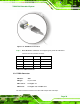
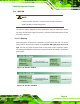
Pin Description Pin Description
1 RED 2 GREEN
3 BLUE 4 NC
5 GND 6 GND
7 GND 8 GND
9 VCC / NC 10 GND
11 NC 12 DDC DAT
13 HSYNC 14 VSYNC
15 DDCCLK
Table 3-13: VGA Connector Pinouts
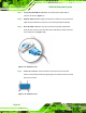
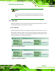
3.10 Powering On/Off the System
WARNING:
Make sure a power supply with the correct input voltage is being fed into
the system. Incorrect voltages applied to the system may cause damage to
the internal electronic components and may also cause injury to the user.
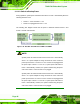
Power on the system: press the power button for 3 seconds
Power off the system: press the power button for 6 seconds
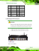
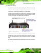
Figure 3-34: Power Button