
User guide

TANK-700 Embedded System
Page 39
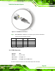
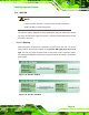
Figure 3-31: USB Device Connection
Step 3: Insert the device connector. Once aligned, gently insert the USB device
connector into the on-board connector.
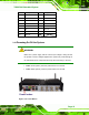
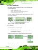
Pin Description Pin Description
1 VCC 5 VCC
2 DATA- 6 DATA-
3 DATA+ 7 DATA+
4 GROUND 8 GROUND
Table 3-12: USB Port Pinouts
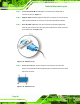
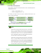
3.9.17 VGA Connector
CN Label: VGA
CN Type:
15-pin Female
CN Location:
See
Figure 1-3
CN Pinouts:
See
Figure 3-33 and Table 3-13
The VGA connector connects to a monitor that accepts VGA video input.