
User guide

TANK-101B/BW Embedded System
Page 17
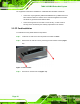
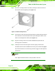
Figure 3-5: Retention Screw Holes
Step 3: Secure the brackets to the system by inserting two retention screws into each
bracket.
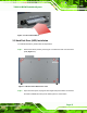
Step 4: Drill holes in the intended installation surface.
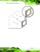
Step 5: Align the mounting holes in the sides of the mounting brackets with the predrilled
holes in the mounting surface.
Step 6: Insert four retention screws, two in each bracket, to secure the system to the
wall.
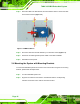
3.5 Mounting the System with Wall Mount Kit
To mount the embedded system onto a wall using the VESA MIS-D 100 wall mount kit,
please follow the steps below.
Step 1: Select the location on the wall for the wall-mounting bracket.
Step 2: Carefully mark the locations of the four bracket screw holes on the wall.
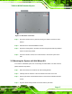
Step 3: Drill four pilot holes at the marked locations on the wall for the bracket retention
screws.
Step 4: Align the wall-mounting bracket screw holes with the pilot holes.