
Manual


SPCIE-5100DX PICMG 1.3 CPU Card
Page 67
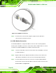
Figure 4-22: LAN Connection
Step 3: Insert the LAN cable RJ-45 connector. Once aligned, gently insert the LAN cable
RJ-45 connector into the on-board RJ-45 connector. Step 0:
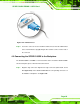
4.8.2 USB Device Connection (Single Connector)
There are two external USB 2.0 connectors. Both connectors are perpendicular to the
SPCIE-5100DX. To connect a USB 2.0 or USB 1.1 device, please follow the instructions
below.
Step 1: Located the USB connectors. The locations of the USB connectors are shown in
Chapter 4.
Step 2: Align the connectors. Align the USB device connector with one of the connectors
on the SPCIE-5100DX. See
Figure 4-23.