
Manual


SPCIE-5100DX PICMG 1.3 CPU Card
Page 62
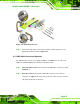
Step 3: Insert the cable connectors. Once the cable connector is properly aligned with
the 26-pin box-header connector on the SPCIE-5100DX, connect the cable
connector to the on-board connector. See
Figure 4-17.
Figure 4-17: LPT Cable Connection
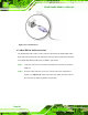
Step 4: Attach the LPT connector bracket to the chassis. The LPT cable connector is
connected to a standard external LPT interface connector. To secure the LPT
interface connector to the chassis please refer to the installation instructions that
came with the chassis.
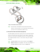
Step 5: Connect LPT device. Once the LPT interface connector is connected to the
chassis, the LPT device can be connected to the LPT interface connector. See
Figure 4-18 Step 0:\