
Manual


SPCIE-5100DX PICMG 1.3 CPU Card
Page 61
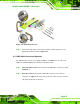
Figure 4-16: Dual RS-232 Cable Installation
Step 3: Secure the bracket. The dual RS-232 connector has two D-sub 9 male
connectors secured on a bracket. To secure the bracket to the chassis please
refer to the reference material that came with the chassis. Step 0:
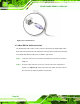
4.7.5 Parallel Port Cable with Slot Bracket (Optional)
The optional parallel port (LPT) cable respectively connects the on-board LPT 26-pin box
header to an external LPT device (like a printer). The cable comprises a 26-pin female
header, to be connected to the on-board LPT box-header, on one side and on the other
side a standard external LPT connector. To connect the LPT cable, please follow the
steps below.
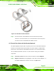
Step 1: Locate the connector. The LPT connector location is shown in Chapter 4.
Step 2: Align the connectors. Correctly align pin 1 on the cable connector with pin 1 on
the SPCIE-5100DX LPT box-header connector. See
Figure 4-17.