
Manual


SPCIE-5100DX PICMG 1.3 CPU Card
Page 37
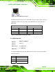
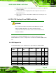
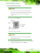
Figure 3-18: RJ-45 Ethernet Connector
The RJ-45 Ethernet connector has two status LEDs, one green and one yellow. The green
LED indicates activity on the port and the yellow LED indicates the port is linked. See
Table 3-19.
SPEED LED ACT/LINK LED
STATUS
DESCRIPTION STATUS
STATUS
OFF 10 Mbps LAN OFF OFF
Green 100 Mbps LAN YELLOW Linked
ORANGE 1000 Mbps LAN BLINKING Data Activity
Table 3-19: RJ-45 Ethernet Connector LEDs
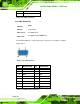
3.3.2 USB Connector
CN Label:
USB_C0 and USB_C1
CN Type:
USB port
CN Location:
See
Figure 3-17
CN Pinouts:
See
Table 3-20
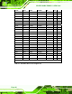
The SPCIE-5100DX has four external USB 2.0 ports. The ports connect to both USB 2.0
and USB 1.1 devices.
PIN NO. DESCRIPTION
1 VCC
2 DATA-
3 DATA+