
Manual


SPCIE-5100DX PICMG 1.3 CPU Card
Page 35
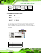
CN Pinouts:
See
Table 3-17
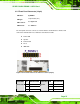
The 2x4 USB pin connectors each provide connectivity to two USB 1.1 or two USB 2.0
ports. Each USB connector can support two USB devices. Additional external USB ports
are found on the rear panel. The USB ports are used for I/O bus expansion.
Figure 3-16: USB Connector Pinout Locations
PIN NO. DESCRIPTION PIN NO. DESCRIPTION
1 VCC (+5V) 2 GND
3 DATA- 4 DATA+
5 DATA+ 6 DATA-
7 GND 8 VCC (+5V)
Table 3-17: USB Port Connector Pinouts
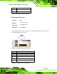
3.3 External Peripheral Interface Connector Panel
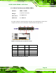
The figure below shows the external peripheral interface connector (EPIC) panel. The
SPCIE-5100DX EPIC panel consists of the following:
2 x RJ-45 LAN connectors
2 x USB connectors
1 x VGA connector