
Manual


SPCIE-5100DX PICMG 1.3 CPU Card
Page 27
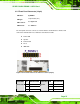
3.2.7 Front Panel Connector (14-pin)
CN Label:
F_PANEL1
CN Type:
14-pin header (2x7)
CN Location:
See
Figure 3-8
CN Pinouts:
See
Table 3-9
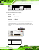
The front panel connector connects to external switches and indicators to monitor and
controls the motherboard. These indicators and switches include:
Power LED
Speaker
Power button
Reset
HDD LED
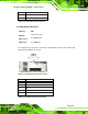
Figure 3-8: Front Panel Connector Pinout Locations (14-pin)
FUNCTION PIN DESCRIPTION FUNCTION PIN DESCRIPTION
1 PWRLED+ 2 SPEAKER+
3 N/C 4 N/C
Power LED
5 PWRLED-
Speaker
6 N/C