
Manual


SPCIE-5100DX PICMG 1.3 CPU Card
Page 19
3.1 Peripheral Interface Connectors
This chapter details all the jumpers and connectors.
3.1.1 SPCIE-5100DX Layout
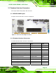
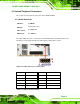
The figures below show all the connectors and jumpers.
Figure 3-1: Connector and Jumper Locations
3.1.2 Peripheral Interface Connectors
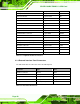
The table below lists all the connectors on the board.
Connector Type Label
Audio connector 10-pin header J_AUDIO1
Battery connector 2-pin wafer BAT1
Cooling fan connector, CPU 4-pin wafer CPU_FAN1
Cooling fan connector, CPU 4-pin wafer CPU_FAN2
Cooling fan connector, Northbridge 4-pin wafer MCH_FAN1
CPU 12 V power connector 8-pin connector ATX_12V1
Digital input/output connector 10-pin header DIO1
DIMM slot (Registered ECC) 240-pin socket CHA_DIMM1
DIMM slot (Registered ECC) 240-pin socket CHA_DIMM2
DIMM slot (Registered ECC) 240-pin socket CHB_DIMM1
DIMM slot (Registered ECC) 240-pin socket CHB_DIMM2