
User guide
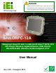
Table Of Contents
- 1 Introduction
- 2 Unpacking
- 3 Installation
- 4 OSD
- 5 BIOS Setup
- 6 System Maintenance
- A Interface Connectors
- B Safety Precautions
- C BIOS Options
- D Terminology
- E Watchdog Timer
- F Hazardous Materials Disclosure
SAILORPC-12A Panel PC
Page ix
List of Tables
Table 1-1: Technical Specifications..............................................................................................6
Table 2-1: Packing List.................................................................................................................11
Table 2-2: Packing List.................................................................................................................12
Table 3-1: Reset CMOS ................................................................................................................17
Table 3-2: AT/ATX Power Selection............................................................................................18
Table 3-3: CF Mode Selection......................................................................................................19
Table 3-4: COM2 RS-232/422/485 Setup (JP17) .........................................................................20
Table 3-5: COM2 RS-232/422/485 Setup (JP18) .........................................................................20
Table 3-6: COM2 Serial Port Pinouts ..........................................................................................21
Table 3-7: Panel Resolution Selection........................................................................................22
Table 3-8: LAN Port Pinouts........................................................................................................24
Table 3-9: Serial Port Pinouts......................................................................................................24
Table 3-10: CAN-bus & Audio Connector Pinouts ....................................................................25
Table 3-11: USB Port Pinouts......................................................................................................26
Table 3-12: Power Connector Pinouts........................................................................................26
Table 5-1: BIOS Navigation Keys................................................................................................37