
User Manual

PPC-51xxA-H61 Panel PC
Page 59
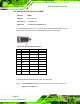
Pin Description Pin Description
6 USB3P0_RXDP1 15 USB3P0_RXDP2
7 GND 16 GND
8 USB3P0_TXDN1 17 USB3P0_TXDN2
9 USB3P0_TXDP1 18 USB3P0_TXDP2
Table 3-10: USB 3.0 Port Pinouts
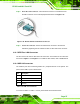
3.13.8 VGA Connector
The VGA connector connects to a monitor that accepts VGA video input. The pinouts of
the VGA connector is shown below.
Figure 3-40: VGA Connector
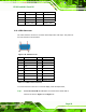
Pin Description Pin Description
1 RED 2 GREEN
3 BLUE 4 NC
5 GND 6 GND
7 GND 8 GND
9 5V 10 GND
11 NC 12 DDCDAT
13 HSYNC 14 VSYNC
15 DDCCLK
Table 3-11: VGA Connector Pinouts
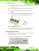
To connect the PPC-51xxA-H61 to a second display, follow the steps below,
Step 1: Locate the female DB-15 connector. The location of the female DB-15
connector is shown in
7Figure 1-5 and Figure 1-6.