
User Manual

PPC-51xxA-H61 Panel PC
Page 57
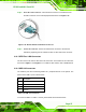
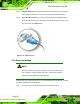
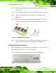
Step 2: Insert the serial connector. Insert the DB-9 connector of a serial device into
the DB-9 connector on the external peripheral interface. See
7Figure 3-38.
Figure 3-38: RS-232/422/485 Serial Device Connector
Step 3: Secure the connector. Secure the serial device connector to the external
interface by tightening the two retention screws on either side of the connector.
3.13.5 SFP Fiber LAN Connectors
The PPC-51xxA-H61 has two SFP fiber LAN connectors. The locations of the connectors
are shown in
7Figure 1-5 and Figure 1-6. To install an SFP module, refer to Section 3.12.
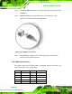
3.13.6 USB 2.0 Connectors
The USB 2.0 ports are for attaching USB 2.0/1.1 peripheral devices to the system. The
pinouts of the USB 2.0 port is shown below.
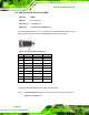
Pin Description
1 VCC
2 DATA-
3 DATA+
4 GROUND
Table 3-9: USB 2.0 Port Pinouts
To connect a USB 2.0 or USB 1.1 device, please follow the instructions below.