
User Manual

PPC-51xxA-H61 Panel PC
Page 53
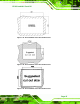
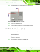
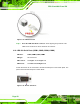
3.13.2 RJ-45 LAN Connectors
The RJ-45 LAN connectors allow connections to external networks. The pinouts of the
RJ-45 LAN connector is shown below.
Pin Description Pin Description
1 MDIA3- 2 MDIA3+
3 MDIA2- 4 MDIA1-
5 MDIA1+ 6 MDIA2+
7 MDIA0- 8 MDIA0+
Table 3-5: LAN Pinouts
Figure 3-33: RJ-45 LAN Connector
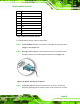
Each RJ-45 LAN connector has two status LEDs, one green and one yellow. See
7Figure 3-33.
LED Description LED Description
A on: linked
blinking: data is being sent/received
B off: 10 Mb/s
green: 100 Mb/s
orange: 1000 Mb/s
Table 3-6: RJ-45 LAN Connector LEDs
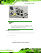
To connect the PPC-51xxA-H61 to a network through the RJ-45 LAN connectors, follow
the steps below.
Step 1: Locate the RJ-45 connectors. The locations of the RJ-45 connectors are
shown in
7Figure 1-5 and Figure 1-6.
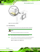
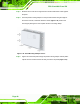
Step 2: Align the connectors. Align the RJ-45 connector on the LAN cable with one of
the RJ-45 connectors on the PPC-51xxA-H61. See
7Figure 3-34.