
User Manual

PPC-51xxA-H61 Panel PC
Page 116
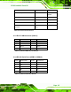
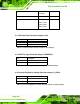
6.2.20 Touch Panel Connector (TOUCH1)
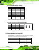
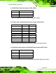
6.2.21 USB 2.0 Connectors (USB1/USB2/USB3/USB4)
PIN NO. DESCRIPTION PIN NO. DESCRIPTION
1 VCC 2 GND
3 DATA- 4 DATA+
5 DATA+ 6 DATA-
7 GND 8 VCC
2
8
y y y y
y y y y
1
7
Table 6-22: USB 2.0 Connector (USB1/USB2/USB3/USB4) Pinouts
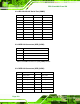
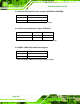
6.3 External Interface Panel Connectors
The table below lists the rear panel connectors on the PPC-51xxA-H61 motherboard.
Pinouts of these connectors can be found in the following sections.
Connector Type Label
Audio connector (line-out and mic-in) Audio jack AUDIO1
RJ-45 LAN connectors RJ-45 LAN1/2
Reset button Push button RST_SW1
PIN NO. 8-Wire 4-Wire 5-Wire
1 Right Sense N/A N/A
2 Left Sense N/A N/A
3 Bottom Sense N/A N/A
4 Top Sense N/A Sense (S)
5 Right Excite Right LR (X)
6 Left Excite Left LL (L)
7 Bottom Excite Bottom UR (Y)
8 Top Excite Top UL (Y)
9 GND GND GND
Table 6-21: Touch Panel Connector ( TOUCH1) Pinouts