
User Manual

PPC-51xxA-H61 Panel PC
Page 110
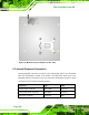
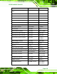
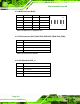
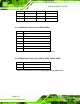
6.2.4 DIO Connector (DIO1)
PIN NO. DESCRIPTION PIN NO. DESCRIPTION
1 GND 2 VCC
3 Output 3 4 Output 2
5 Output 1 6 Output 0
7 Input 3 8 Input 2
9 Input 1 10 Input 0
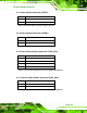
2 10
y y y y y
y y y y y
1 9
Table 6-5: DIO Connector (DIO1) Pinouts
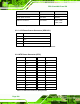
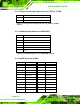
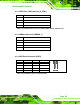
6.2.5 Fan Connector (CPU_FAN1/SYS_FAN1/SYS_FAN2/SYS_FAN3)
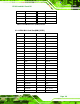
6.2.6 I2C Connector (I2C_1)
PIN NO. DESCRIPTION
1 GND
2 +12V
3 SENSE
4 CONTROL
Table 6-6: Fan Connector Pinouts
PIN NO. DESCRIPTION
1 +5V_DUAL
2 PCH_GP38_PU
3 PCH_GP39_PU
4 GND
Table 6-7: Fan Connector (I2C_1) Pinouts