
User Manual
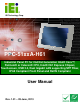

PPC-51xxA-H61 Panel PC
Page x
List of Figures
Figure 1-1: PPC-51xxA-H61 Panel PC...........................................................................................2
Figure 1-2: Front View....................................................................................................................4
Figure 1-3: Rear View .....................................................................................................................5
Figure 1-4: Top View.......................................................................................................................5
Figure 1-5: PPC-5150A-H61/PPC-5170A-H61 Bottom View........................................................7
Figure 1-6: PPC-5190A-H61 Bottom View ....................................................................................8
Figure 1-7: Left View.......................................................................................................................9
Figure 1-8: Right View....................................................................................................................9
Figure 1-9: Internal Components ................................................................................................10
Figure 1-10: PPC-5150A-H61 Dimensions (mm)........................................................................11
Figure 1-11: PPC-5170A-H61 Dimensions (mm)........................................................................12
Figure 1-12: PPC-5190A-H61 Dimensions (mm)........................................................................13
Figure 3-1: PPC-5150A-H61 Back Cover Retention Screws.....................................................25
Figure 3-2: COM1 to COM5 Pin 9 Setting Jumper Locations...................................................28
Figure 3-3: COM5 RS-232/422/485 Serial Port Selection Jumper Location............................29
Figure 3-4: HDD Bracket Retention Screws...............................................................................30
Figure 3-5: HDD Retention Screws .............................................................................................31
Figure 3-6: Replacing the HDD Bracket .....................................................................................31
Figure 3-7: CompactFlash® Cover Plate....................................................................................32
Figure 3-8: Installing the CompactFlash® Card ........................................................................32
Figure 3-9: Replacing the CompactFlash® Cover Plate...........................................................33
Figure 3-10: Optical Drive Bracket Retention Screws ..............................................................34
Figure 3-11: Optical Drive Blank Plate Assembly .....................................................................34
Figure 3-12: Optical Drive Screws ..............................................................................................35
Figure 3-13: Optical Drive SATA Cable ......................................................................................35
Figure 3-14: Replacing the Optical Drive Bracket.....................................................................36
Figure 3-15: Installing the PCI Riser Card..................................................................................38
Figure 3-16: Expansion Slot Retention Screw...........................................................................38
Figure 3-17: Installing the PCI Card............................................................................................39
Figure 3-18: Installing the PCIe Riser Card................................................................................41
Figure 3-19: Expansion Slot Retention Screw...........................................................................41