
Instruction Manual


PPC-5152-D525 Falt-bezel Panel PC
Page 54
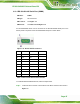
Figure 3-40: VGA Connector
Pin Description Pin Description
1 RED 2 GREEN
3 BLUE 4 NC
5 GND 6 GND
7 GND 8 GND
9 CRT_VCC 10 GND
11 NC 12 5VDDC DAT
13 HSYNC 14 VSYNC
15 5VDDCCLK
Table 3-10: VGA Connector Pinouts
To connect the PPC-5152-D525 to a second display, follow the steps below,
Step 1: Locate the female DB-15 connector. The location of the female DB-15 connector
is shown in
6Figure 1-4.
Step 2: Align the VGA connector. Align the male DB-15 connector on the VGA screen
cable with the female DB-15 connector on the external peripheral interface.
Step 3: Insert the VGA connector. Once the connectors are properly aligned with the
insert the male connector from the VGA screen into the female connector on the
PPC-5152-D525. See
6Figure 3-41.