
Instruction Manual


PPC-5152-D525 Falt-bezel Panel PC
Page 50
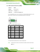
Pin Description Pin Description
2 TXD485# 6 RXD485#
3. N/A 7 N/A
4. TXD485+ 8 RXD485+
Table 3-6: RJ-45 RS-422/485 Serial Port Pinouts
To install the RS-422/485 devices, follow the steps below.
Step 1: Locate the RJ-45 RS-422/485 connector. The location of the RJ-45 RS-422/485
connector is shown in
6Figure 1-4.
Step 2: Insert the RJ-45 connector. Insert the RJ-45 connector on the RJ-45 to DB-9
COM port cable to the RJ-45 RS-422/485 connector on the PPC-5152-D525.
See
6Figure 3-37.
Figure 3-37: RJ-45 RS-422/485 Serial Device Connection
Step 3: Insert the serial connector. Insert the DB-9 connector of a serial device into the
DB-9 connector on the RJ-45 to DB-9 COM port cable.
Step 4: Secure the connector. Secure the serial device connector to the external
interface by tightening the two retention screws on either side of the connector.
Step 5: The DB-9 connector pinouts are listed below.