
Instruction Manual


PPC-5152-D525 Falt-bezel Panel PC
Page 48
Step 2: Insert the serial connector. Insert the DB-9 connector of a serial device into the
DB-9 connector on the external peripheral interface. See
6Figure 3-34.
Figure 3-34: Serial Device Connector
Step 3: Secure the connector. Secure the serial device connector to the external
interface by tightening the two retention screws on either side of the connector.
3.11.6.1 COM3 Mode Select Switch
Jumper Label: U61
Jumper Type:
10-pin DIP switch
Jumper Settings:
See
56Table 3-5
Jumper Location:
See
56Figure 3-35
The COM3 RS-232/422/485 Serial Port Select jumper sets the communication protocol
used by the second serial communications port (COM3) as RS-232, RS-422 or RS-485.
The COM3 RS-232/422/485 Serial Port Select settings are shown in
56Table 3-5.
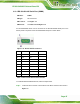
COM3 Mode Settings
RS-232 (Default) OFF: 1, 2, 3, 4, 5
ON: 6, 7, 8, 9, 10
RS-422/485 OFF: 6, 7, 8, 9, 10
ON: 1, 2, 3, 4, 5
Table 3-5: COM3 RS-232/422/485 Serial Port Select Settings