
Instruction Manual


PPC-5152-D525 Falt-bezel Panel PC
Page 44
Step 2: Align the connectors. Align the RJ-45 connector on the LAN cable with one of
the RJ-45 connectors on the PPC-5152-D525. See
6Figure 3-29.
Figure 3-29: LAN Connection
Step 3: Insert the LAN cable RJ-45 connector. Once aligned, gently insert the LAN cable
RJ-45 connector into the on-board RJ-45 connector.
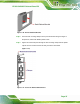
3.11.3 Power Input, 2-pin Terminal Block
CN Label: DC IN
CN Type:
3-pin terminal block
CN Location:
See
6Figure 1-4
CN Pinouts:
See
6Figure 3-30
Connect the leads of a 9 V~36 V DC power supply into the terminal block. Make sure that
the power and ground wires are attached to the correct sockets of the connector.