
Instruction Manual


PPC-5152-D525 Falt-bezel Panel PC
Page 43
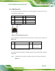
3.11.2 LAN Connector
The LAN connector allows connection to an external network. The pinouts of the RJ-45
LAN connector is shown below.
Pin Description Pin Description
1 MDI0+ 2 MDI0-
3 MDI1+ 4 MDI1-
5 MDI2+ 6 MDI2-
7 MDI3+ 8 MDI3-
Table 3-1: LAN Pinouts
Figure 3-28: RJ-45 Ethernet Connector
The RJ-45 Ethernet connector has two status LEDs, one green and one yellow. See
6Figure 3-28.
LED Description LED Description
A on: linked
blinking: data is being sent/received
B off: 10 Mb/s
green: 100 Mb/s
orange: 1000 Mb/s
Table 3-2: RJ-45 Ethernet Connector LEDs
To connect the PPC-5152-D525 to a network through the RJ-45 LAN connector, follow the
steps below.
Step 1: Locate the RJ-45 connector. The location of the RJ-45 connectors is shown in
6Figure 1-4.