
Owner manual


PPC-37xx-N270 Panel PC
Page 64
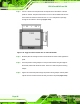
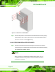
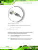
Figure 4-36: USB Device Connection
Step 3: Insert the device connector. Once aligned, gently insert the USB device
connector into the onboard connector. Step 0:
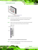
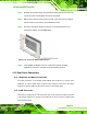
4.14.5 VGA Monitor Connection
The PPC-37xx-N270 has a single female DB-15 connector on the external peripheral
interface panel. The DB-15 connector is connected to a CRT or VGA monitor. To connect
a monitor to the PPC-37xx-N270, please follow the instructions below.
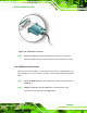
Step 1: Locate the female DB-15 connector. The location of the female DB-15
connector is shown in Chapter 3.
Step 2: Align the VGA connector. Align the male DB-15 connector on the VGA screen
cable with the female DB-15 connector on the external peripheral interface.