
Owner manual


PPC-37xx-N270 Panel PC
Page 58
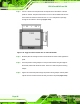
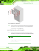
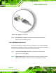
Step 3: Align the retention screw holes on the mounting arm interface with those in the
flat panel PC. The flat panel PC arm mount retention screw holes are shown in
Figure 4-29.
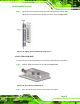
Figure 4-29: Arm Mounting Retention Screw Holes
Step 4: Secure the flat panel PC to the interface pad by inserting four retention screws
through the bottom of the mounting arm interface pad and into the
flat panel PC.Step 0:
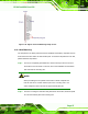
4.13.4 Cabinet and Rack Installation
The PPC-3708A-N270, PPC-3710A-N270 and PPC-3712A-N270 flat panel PC can be
installed into a cabinet or rack. To do this, please follow the steps below.
4.13.4.1 PPC-3708A-N270
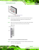
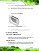
Step 1: Slide the rear chassis of the PPC-3708A-N270 flat panel PC through the
rack/cabinet bracket until the aluminum frame is flush against the front of the
bracket (
Figure 4-30).