
Owner manual


PPC-37xx-N270 Panel PC
Page xii
List of Figures
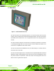
Figure 1-1: PPC-37xx-N270 Panel PC ...........................................................................................2
Figure 1-2: Front View....................................................................................................................5
Figure 1-3: PPC-3712A-N270 Wall-Mounting Bracket Retention Screw Holes.........................6
Figure 1-4: PPC-3708A-N270 Bottom View ..................................................................................7
Figure 1-5: PPC-3710A-N270 Bottom View ..................................................................................7
Figure 1-6: PPC-3712A-N270 Bottom View ..................................................................................7
Figure 1-7: PPC-3712A-N270 Left View ........................................................................................8
Figure 1-8: PPC-3712 Frame Rear View........................................................................................8
Figure 2-1: PPC-3708A-N270 Dimensions (units in mm)..........................................................14
Figure 2-2: PPC-3710A-N270 Dimensions (units in mm)..........................................................15
Figure 2-3: PPC-3712A-N270 Dimensions (units in mm)..........................................................16
Figure 2-4: PPC-3708A SATA Hard Disk Drive Bay...................................................................18
Figure 2-5: PPC-3708A CompactFlash® Slot.............................................................................18
Figure 2-6: PPC-3708A COM Ports .............................................................................................19
Figure 2-7: PPC-3708A RJ-45 Ethernet Connectors .................................................................20
Figure 2-8: PPC-3708A External USB Ports...............................................................................21
Figure 2-9: PPC-3708A PS/2 Connector.....................................................................................21
Figure 2-10: LCD Screen..............................................................................................................22
Figure 2-11: PPC-3708A VGA Connector...................................................................................23
Figure 2-12: PPC-3708A Audio Jack...........................................................................................23
Figure 2-13: Power Connector ....................................................................................................24
Figure 4-1: PPC-3708 Back Cover Retention Screws ...............................................................34
Figure 4-2: PPC-3710 Back Cover Retention Screws ...............................................................34
Figure 4-3: PPC-3712 Back Cover Retention Screws ...............................................................35
Figure 4-4: CF Card Installation ..................................................................................................36
Figure 4-5: PPC-3708 HDD Bracket Retention Screws (Tope Panel) ......................................37
Figure 4-6: PPC-3708 HDD Bracket Retention Screws (Inside) ...............................................37
Figure 4-7: PPC-3708 HDD Retention Screws ...........................................................................37
Figure 4-8: PPC-3710 HDD Bracket Retention Screws .............................................................38
Figure 4-9: PPC-3710 HDD Retention Screws ...........................................................................39