
User Manual


POC-17i/19i Series
Page 40
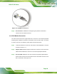
Figure 3-20: VGA Connector
Step 4: Secure the connector. Secure the DB-15 VGA connector from the VGA
monitor to the external interface by tightening the two retention screws on either
side of the connector. Step 0:
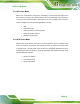
3.9 AT/ATX Mode Selection
AT and ATX power modes can both be used on the POC-17i/19i Series. The selection is
made through an AT/ATX switch on bottom panel (
Figure 3-21). To select AT mode or
ATX mode, follow the steps below.
Step 1: Locate the AT/ATX switch on the bottom panel (
Figure 3-21).
Figure 3-21: AT/ATX Switch Location
Step 2: Adjust the switch according to the preferred setting.